Page | 24
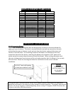
REPLACEMENT PARTS LIST
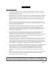
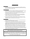
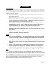
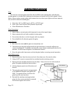
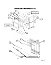
Diagram
No.
Description PartNo. PerUnit
1 AirControlSlider AC‐17ACS 1
2 OutsideAirAdapter AC‐17OAA 1
3 RightVermiculitePanel AC‐17RBR 1
4 LeftVermiculitePanel AC‐17RBL 1
5 RearVermiculitePanel AC‐17RBB 2
6 9"x4"x1.25"Fir ebrick AC‐SB 4
7 TopVermiculiteBaffle AC‐17RBT 1
8 DoorGasket[5/8"diaHD] AC‐DGKNC 1
9 WindowGasket AC‐GGK 1
10 CeramicGlassPanel AC‐G40 1
11 WindowRetainingBrackets AC‐GS16 2
12 CastIronDoor CA‐16 1
13 SecondaryTube (Front) AC‐17BTF 1
14 UpperRefractoryBaffle AC‐17URBVL 1
15 SecondaryTube (Rear) AC‐17BTR 1
NotShown LargeSpringHandle AC‐SH(Brass) 1
AC‐SHN(Nickel)
NotShown AirControlSpringHandle AC‐SH4(Brass) 1
AC‐SH4N(Nickel)
OPTIONAL ACCESSORIES
AC‐16ConvectionBlower
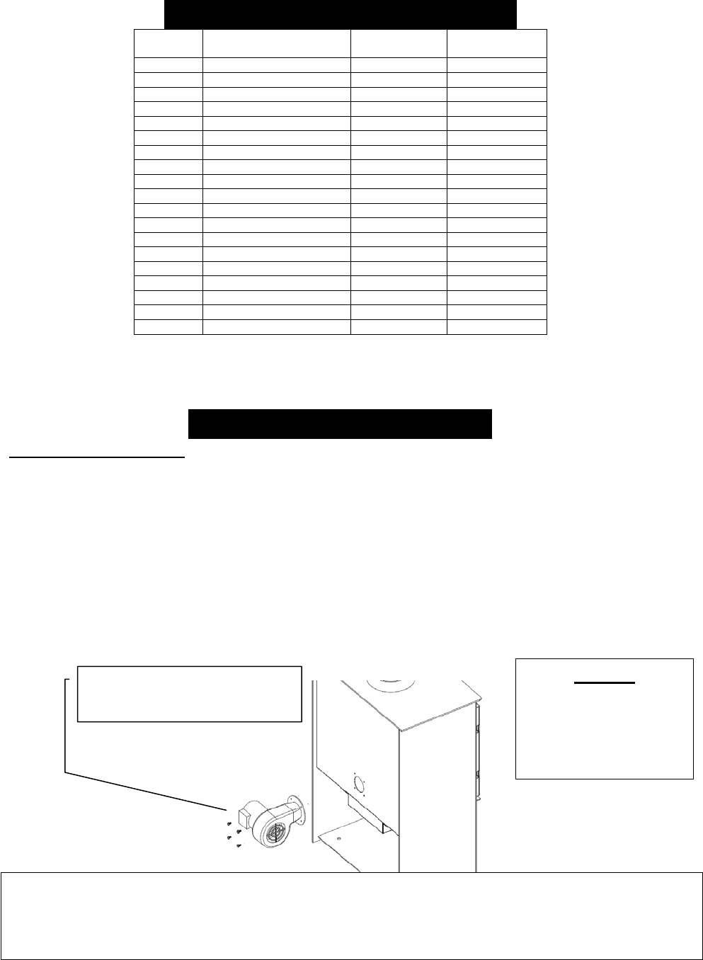
TheTranquilitywoodstovewasalsodesignedforusewithaconvectionblowerfor
additionalheatcirculation.Thestoveisconstructedwithrearandtopconvectionchannels
whichallowtheroomairblowertopickupheatfromthehottestregionsofthestoveand
transferitintothehome.Themountingscrewsfortheblowerareinstalledintotherear
convectionchannelatthefactory;mountingthebloweronlyrequiresa5/16”openendor
socketwrenchtoremovethesescrewsandinstalltheblower.Whenroutingthepowercord,
takecaretokeepawayfromhotareasofthe
unitandrememberthatthisblowerisforuseonly
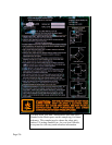
withthestove.Pleaseseethediagrambelowforclarificationontheroomairblower
installation.
(4)5/16”head,selftapping
screws(pre‐installedinunit).
Warning
Disconnectthe
electricalpowerfrom
thefanbefore
installation.
The optional heat circulation blower on this stove requires periodic lubrication; this lubrication
should be performed no less than every three months of normal operation. To properly lubricate the
blower, use an eye dropper or similar dispensing device to drip 5-7 droplets of SAE 20 oil into the
oil
p
ort on the side of the blower motor.


