


9
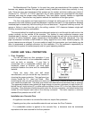
Installation on a Combustible Floor
If the appliance is to be installed on a combustible floor or a combustible floor covering, it must
be installed on a 1” thick non-combustible millboard floor protector or a durable equivalent, with a
“R” factor of no less than “2.” The pad must be installed beneath the unit, extending 16” (U.S.) on
the side equipped with a door, and 8” on all other sides. The pad must cover any horizontal
chimney connector runs and extend 2” beyond each side.
Alternate Floor Protection:
An easy means of determining if a proposed alternate floor protector meets requirements is to
follow this procedure:
1) Convert specification to R-value:
i R-value is given – no conversion is needed
ii k-factor is given with a required thickness (T) in inches: R = 1/k x T
iii C-factor is given: R = 1/C
2) Determine the R-value of the proposed alternate floor protector:
i Use the correct formula given in step 1 (above) to convert values not expressed as
“R.”
ii For multiple layers, add R-values of each layer to determine overall R-value.
3) If the overall R-value of the system is greater than the R-value of the specified floor
protector, the alternate is acceptable.
EXAMPLE:
The specified floor protector should be ¾” thick material with a k-factor of 0.84. The proposed
alternate is 4” brick with a C-factor of 1.25 over 1/8” mineral board with a k-factor of 0.29.
Step (a): Use formula above to convert specification to R-value. R = 1/k x T = 1/0.84 x .75 =
0.893
Step (b): Calculate R of proposed system.
4” brick of C = 1.25, therefore R brick = 1/C =1/1.25 = 0.80
1/8” mineral board of k = 0.29, therefore Rmin.bd. = 1/0.29 x 0.125 = 0.431
Total R = Rbrick + Rmineral board = 0.8 + 0.431 = 1.231
Step (c): Compare proposed system of R of 1.231 to specified R of 0.893. Since proposed
system R is greater than required, the system is acceptable.
Definitions:
Thermal conductance = C = Btu = W
(hr)(ft
2
)(deg F) (m
2
)(deg K)
Thermal conductivity = k = (Btu)(inch) = W = Btu
(hr)(ft
2
)(deg F) (m)(deg K) (hr)(ft)(deg F)
Thermal resistance = R = (ft
2
)(hr)(deg F) = (m
2
)(deg K)
Btu W
2. Wall Protection
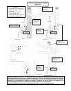
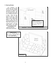
Please see Illustration 1 for clearances to walls. In some areas local codes may require thirty-
six inches (36”) from a combustible, therefore it is very important that you check with local officials.
If you need to place your unit closer to a combustible wall, some protection will be necessary. If an
approved wall board is used this will reduce your clearance by two thirds (2/3); however, a one
inch (1”) air space has to be between the board and the wall. If you have a ceiling flue hook-up,
you will need protection from the floor to the ceiling if you do not meet the normal clearances. If
you have a wall flue hook up, you will need wall protection at least twelve inches (12”) above the
wall thimble.