


Operating Instructions and Owner’s ManualEnerco | Compact Unit Heater
9
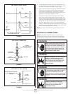
F – VENTING USING A MASONRY CHIMNEY
The following additional requirements apply when a lined masonry
chimney is being used to vent the compact unit heater.
1. Masonry chimneys used to vent Category I units heaters
must be either tile-lined or lined with a listed metal lining
system or dedicated gas vent. Unlined masonry chimneys are
prohibited. A category I appliance must never be connected
to a chimney that is servicing a solid fuel appliance. If a
fireplace chimney flue is used to vent this appliance, the
fireplace opening must be permanently sealed.
2. A fan assisted unit heater may be commonly vented into an
existing lined masonry chimney provided:
• The chimney is currently serving at least one draft-hood
equipped appliance.
• The vent connector and chimney are sized in accordance
with venting tables in the (American) National Fuel Gas
Code ANSI Z223.1 or (Canada) CSA B149.1 Natural Gas
and Propane Installation Code.
IMPORTANT Single appliance venting of a fan assisted unit
heater into a tile lined masonry chimney (interior or outside wall)
is prohibited. The chimney must rst be lined with either type B-1
vent or an insulated single wall flexible vent lining system, sized
in accordance with venting tables in the (American) National Fuel
Gas Code ANSI Z223.1 or (Canada) CSA B149.1 Natural Gas and
Propane Installation Code.
3. A type B-1 vent or masonry chimney liner shall terminate
above the roof surface with a listed cap or a listed roof
assembly in accordance with the terms of their respective
listings and the vent manufacturer’s instructions.
4. Do not install a manual damper, barometric draft regulator, or
flue restrictor between the unit heater and the chimney.
5. If type B-1 double-wall vent is used inside a chimney, no other
appliance can be vented into the chimney. Outer wall of type
B-1 vent pipe must not be exposed to ue products.
6. Insulation for the flexible vent pipe must be an encapsulated
fiberglass sleeve recommended by the flexible vent pipe
manufacturer.
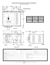
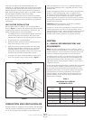
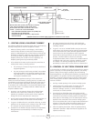
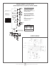
HORIZONTAL VENTING - RESIDENTIAL INSTALLATION
UPWARD SLOPE
INDUCED DRAFT BLOWER
12 INCHES
MIN. (30.5CM)
VENT TERMINATION CAP
LISTED THIMBLE THROUGH
COMBUSTION WALL
MAY BE SINGLE WALL (26 GSG) GALV. OR EQUIV. STAINLESS
STEEL SEALED ACCORDING TO THESE INSTALLATION
INSTRUCTIONS OR A SINGLE SECTION OF TYPE B-1 VENT.
SLOPED: + 1/4 INCH FOR 1 FOOT RUN MINIMUM.
NOTE - MINIMUM HORIZONTAL LENGTH 3FT. (914MM), NOT
INCLUDING CAP FOR TERMINATION.
MAXIMUM HORIZONTAL LENGTH 5FT. (1.5M) PLUS ONE
90-DEGREE ELBOW.
COMMON VENTING NOT ALLOWED WHEN HORIZONTALLY VENTING THE UNIT HEATER.
FLUE TRANSITION
(PROVIDED)
FIGURE 6
7. The space between liner and chimney wall should NOT
be insulated with puffed mica or any other loose granular
insulating material.
8. If type B-1 vent or an insulated exible vent pipe cannot be
used as liners, the chimney must be rebuilt to accommodate
one of these methods or some alternate approved method
must be found to vent the appliance. When inspection
reveals that an existing chimney is not safe for the intended
purpose, it shall be rebuilt to conform to nationally
recognized standards, lined or relined with suitable materials
or replaced with a gas vent or chimney suitable for venting
unit heaters. The chimney passageway must be checked
periodically to ensure that it is clear and free of obstructions.
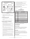
G – REMOVAL OF UNIT FROM COMMON VENT
In the event that an existing unit heater is removed from a venting
system commonly run with separate gas appliances, the venting
system is likely to be too large to properly vent the remaining
attached appliances. The following test should be conducted while
each appliance is in operation and the other appliances are not in
operation, yet remain connected to the common venting system.
If the venting system has been installed improperly, the system
must be corrected.
1. Seal any unused openings in the common venting system.
2. Visually inspect the venting system for proper size and
horizontal pitch. Determine there is no blockage or
restriction, leakage, corrosion, or other deficiencies which
could cause an unsafe condition.
3. If practical close all building doors and windows and all
doors between the space in which the appliances remaining
connected to the common venting system are located and
other spaces of the building. Turn on clothes dryers and any
appliances not connected to the common venting system.
Turn on any exhaust fans, such as range hoods and bathroom
exhausts, so they will operate at maximum speed. Do not
operate a summer exhaust fan. Close fireplace dampers.
4. Follow the lighting instructions. Place the appliance being
inspected in operation. Adjust thermostat so appliance will
operate continuously.