


Operating Instructions and Owner’s ManualEnerco | Compact Unit Heater
13
minimum of 5.0” w.c. for natural gas or 10.4” w.c. for LP/
propane gas should be maintained for proper unit operation.
2. After line pressure has been checked and adjusted, check
manifold pressure. Correct manifold pressure is shown on the
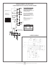
unit rating plate. See figure 10 for gas pressure adjustment
screw location. A natural gas to LP/propane gas changeover
kit is required to convert unit. Refer to installation instructions
provided with changeover kit for conversion procedure.
LIMIT CONTROL
The limit control switch is factory set and not field adjustable.
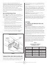
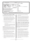
LOUVER VANE ADJUSTMENTS
Rotate louver vanes to direct airflow upward, downward, straight,
or any combination of these directions. When unit is installed
in an inverted position, louvers may be positioned in the same
manner.
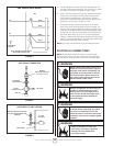
COMBUSTION AIR PRESSURE SWITCH
This pressure switch checks for proper combustion air blower
operation before allowing an ignition trial. The switch is factory set
and no field adjustment is necessary.
FLAME ROLLOUT SWITCH
The flame rollout switch(es) are located on the burner box top,
behind the ignition control board. This normally closed switch
opens on a temperature rise. Check for adequate combustion air
before manually resetting switch.
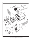
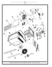
SERVICE
CAUTION Turn off gas and electrical power to unit before
performing any maintenance or service operations on this unit.
Remember to follow lighting instructions when putting unit back
into operation after service or maintenance.
If any of the original wire as supplied with the appliance must
be replaced, it must be replaced with wiring material having a
temperature rating of at least 105°C.
Do not use this appliance if any part has been under water.
Immediately call a qualified service technician to inspect the
appliance and replace any gas control which has been under
water.
BURNERS
1. Periodically examine burner flames for proper appearance
during the heating season.
2. Before each heating season examine the burners for any
deposits or blockage that may have occurred.
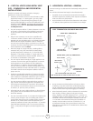
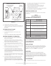
3. Clean burners as follows:
• Turn off both electrical and gas supplies to unit.
• Disconnect gas supply piping, high tension and sensor
leads. Remove gas manifold. Remove burner tray.
• Clean burners as necessary. Make sure that burner
heads line up properly to ensure flame crossover. Check
spark gap on electrode and adjust if required. The gap
should be between 0.110 inch and 0.140 inch (2.79mm
to 3.56mm). The gap may be checked with appropriately
sized twist drills or feeler gauges.
• Reinstall burner tray, gas manifold, high tension and
sensor leads. Reconnect gas supply piping.
• Restore electrical power and gas supply. Follow lighting
instructions to light unit. Check burner flame.
FLUE PASSAGEWAY AND FLUE BOX
The flue passages and flue box should be inspected and cleaned
prior to each heating season. The sequence of operation should
be as follows:
1. Turn off both electrical and gas supply to unit.
2. Disconnect combustion air blower wiring.
3. Remove screws securing flue box to unit. Remove flue box. If
necessary, remove blower assembly from flue box. Clean flue
box with wire brush.
4. Remove turbulator retention bracket and turbulators. Clean
turbulators with wire brush.
5. Remove burners as described in section “BURNERS” section.
6. Clean tubes with a wire brush.
7. Reassemble unit. The combustion air and flue box gaskets
should also be replaced during reassembly.
8. Restore electrical power and gas supply. Follow lighting
instructions to light unit. Check operation of unit.
COMBUSTION AIR BLOWER
Under normal operating conditions, the combustion air blower
should be checked and cleaned prior to the heating season with
the power supply disconnected. Use a small brush to clean blower
wheel.
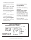
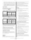
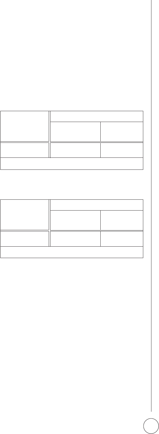
TABLE 4
NATURAL GAS MANIFOLD PRESSURES - IN.WG. (KPA)
TABLE 5
LP/PROPANE GAS MANIFOLD PRESSURES - IN.WG. (KPA)
ALTITUDE FT. (M)
45/75 10 (2.49)* 8.0 (1.99)
MHU45/75 HSU45/75 0-2000 2000-4500
(0-610) (610-1370)
ALTITUDE FT. (M)
45/75 4.0 (0.99)* 3.6 (0.89)
MHU45/75 HSU45/75 0-2000 2000-4500
(0-610) (610-1370)
*No adjustment required.
*No adjustment required.