


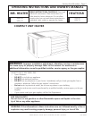
Operating Instructions and Owner’s ManualEnerco | Compact Unit Heater
7
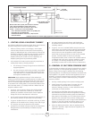
B – VERTICAL VENTS USING METAL VENT
PIPE – COMMERCIAL AND RESIDENTIAL
INSTALLATIONS
MHU/HSU compact unit heaters are listed as Category I
appliances for vertical vent installations.
1. MHU/HSU unit heaters are to be used with NFPA- or ANSI-
approved chimneys, U.L. listed type B-1 gas vents, single
wall metal pipe, or listed chimney lining system for gas
venting where applicable, as well as the modifications and
limitations listed in figure 2. Seal single wall vent material
according to the section A - General Recommendations
and Requirements.
2. The vent connector shall be 3” (76mm) diameter on 45 units.
In all cases, a flue transition piece (supplied) is required to
fit over the outlet of the induced draft assembly on the
appliance.
3. Keep the vent connector runs as short as possible with
a minimum number of elbows. Refer to the (American)
National Fuel Gas Code ANSI Z223.1 or (Canada) CSA B149.1
Natural Gas and Propane Installation Code for maximum
vent and vent connector lengths. Horizontal run of the vent
connector from the induced draft blower to the chimney/vent
cannot exceed the values in table 2.
4. When the length of a single wall vent, including elbows,
exceeds 5 feet (1.5m), the vent shall be insulated along
its entire length with a minimum of 1/2” thick foil faced
berglass 1-1/2# density insulation. If a single wall vent is
used in an unheated area it shall be insulated. Failure to do
so will result in condensation of flue gases.
5. The unit may be vented vertically as a single appliance or as
a common vent with other gas-red appliances. In common
venting situations, vent connectors for other appliances
must maintain a 4” (100mm) vertical separation between
the vent connectors. Refer to common venting tables in the
(American) National Fuel Gas Code ANSI Z223.1 or (Canada)
CSA B149.1 Natural Gas and Propane Installation Code for
proper vent size.
6. Clearance to combustible material is 6” (152mm) for single
wall vent material except where a listed clearance thimble is
used. Clearance to combustible material for type B-1 vent or
factory-built chimney is per manufacturer’s instructions.
7. The vent connector shall be supported without any dips or
sags. Vertical vents shall be supported in accordance with
their listing and manufacturers’ instructions. All horizontal
vent connector runs shall have a slope up to the vertical vent
of at least 1/4” per foot (1mm per 50mm).
8. All vertical type B-1 vents, single wall vents, or listed chimney
lining system must be terminated with a listed vent cap or
listed roof assembly.
9. The vent must extend at least 3’ (1m) above the highest point
where it passes through a roof of a building and at least 2’
(0.6m) higher than any part of a building within a horizontal
distance of 10’ (3.05m) unless otherwise specified by the
(American) National Fuel Gas Code, ANSI Z223.1 or (Canada)
CAN/CGA-B149 Installation Code. The vent must extend at
least 5’ (1.6m) above the highest connected equipment flue
collar.
C – HORIZONTAL VENTING – GENERAL
Common venting is not allowed when horizontally venting the unit
heater.
The minimum horizontal vent length is three feet (914mm).
1. If possible, do not terminate the horizontal vent through a
wall that is exposed to prevailing wind. Exposure to excessive
winds can affect unit performance.
2. Vent termination must be free from obstructions and at least
12” (306mm) above grade level and maximum snow height.
3. Do not terminate vent directly below roof eaves or above
a walkway, or any other area where condensate dripping
may be troublesome and may cause some staining. Avoid
windows where steam may cause fogging or ice buildup.
4. When horizontally vented, minimum clearance for termination
from any door, window, gravity air inlet, gas or electric
meter, regulators, and relief equipment is 4 ft. (1.2m) for U.S.
installations. Refer to NFPA 54/ANSI Z223.1 in the U.S.A. and
CSA B149.1 Natural Gas and Propane Installation Code and
.2 in Canada or with authorities having local jurisdiction. In
Canada, vent termination must have a minimum 6 ft. (1.8
m) horizontal clearance from gas and electric meters and
relief devices as specified in the Canadian B149.1, Natural Gas
Installation Code.
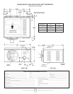
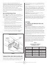
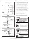
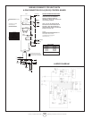
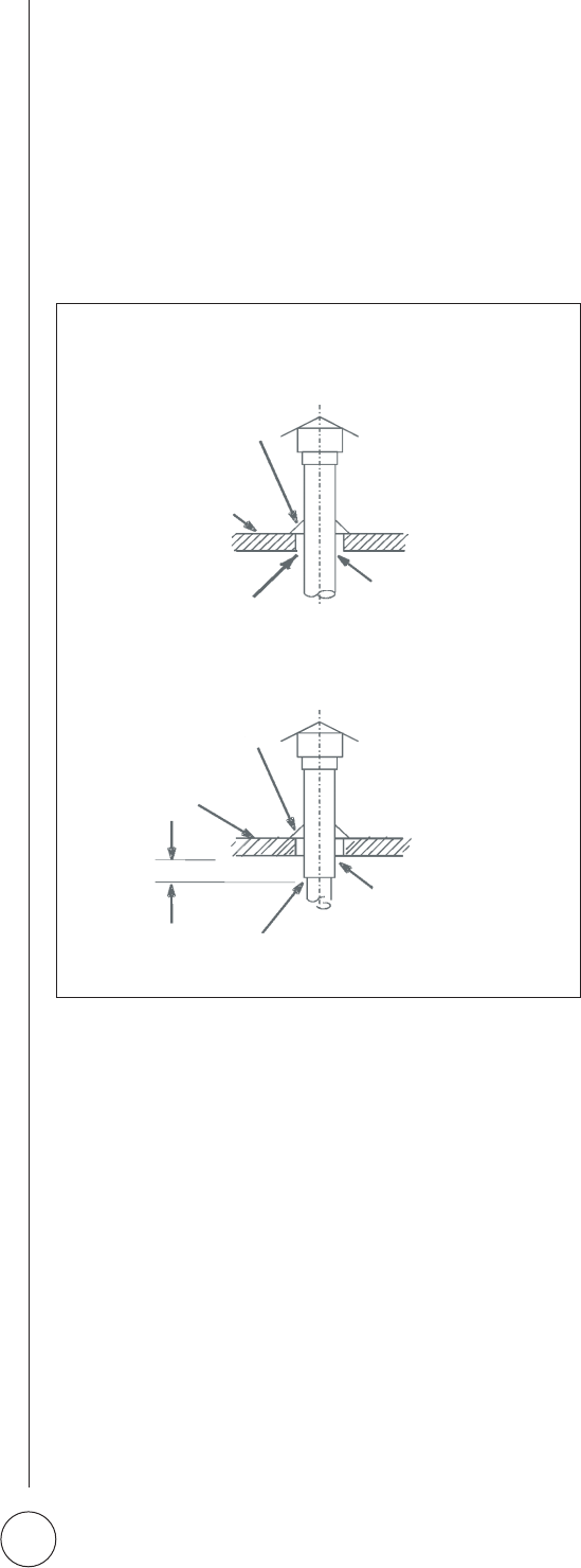
VENT TERMINATION ON SINGLE WALL VENT
SINGLE WALL TERMINATION
DOUBLE WALL (TYPE B-1) TERMINATION
ROOF FLASHING
ROOF PITCHED
FROM 0” TO 45”
SHALL NOT BE A
CONCEALED SPACE
2” CLEARANCE
THIMBLE
ROOF FLASHING
ROOF PITCHED
FROM 0” TO 45”
12” MAX
CLEARANCE TO BE AS
SPECIFIED ON TYPE “B”
VENT PIPE
SEAL JOINT BETWEEN SINGLE WALL VENT
AND “B”VENT AND THE ANNULAR SPACE OF THE “B” VENT
FIGURE 2