


5
OperatingInstructionsandOwner’sManualEnerco Group, Inc. | Gas-Fired Infra-Red Space Heaters
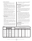
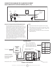
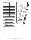
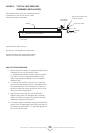
CONNECTION DIAGRAM FOR FLAME ROD CURRENT
FOR FLAME RECTIFICATION SYSTEMS (DSP-5, A5)
MEANS OF PROVING ADEQUATE GROUNDING AREA
The proper flame-rod-to-ground-area ratio cannot
alwaysbedeterminedbyvisualexaminationorphysical
measurement. A positive means of checking the instal-
lation is the measurement of the flame rod current
underactualringconditions.Itisdenitelyrecom-
mended that the installer measure the current flow be-
tween the lead of the flame rod unit and the terminal
inthecontrolterminalboard(seeFigure3).Measure
the current with a DC Microammeter or equal. We
recommend a steady output of .9 microamperes or
more. A steady flow of current in this amount under
actualringconditionswillgenerallyindicateadequate
grounding of the pilot flame.
NOTE:
1. Read all control data sheet supplied with this heater.
2. Check flame rod for any contact to heater parts. Flame
rod must be free of any contact to heater. Contact with
heater will short circuit flame rod.
3. Cracked porcelain on flame rod will short circuit sensor.
Replace flame rod.
Figure 3 – Using a microammeter to prove adequate grounding area.
Gas
Flame
Flame
Rod
Flame
Rod Assy.
Microammeter
Control
Terminal For
Flame Rod
Loadwire
G
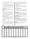
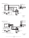
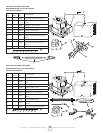
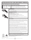
THERMOSTAT
Thermostat
Powerpile Thermocouple
Honeywell Q313A
Factory wired
Powerpile Gas Valve – Honeywell VS820
WIRE
SIZES
MAXIMUM
LENGTH
OF WIRE
CABLE
NO 18 15 FEET
NO 16 30 FEET
NO 14 50 FEET
CAUTION TO INSTALLER
NEVER CONNECT POWERPILE
GAS VALVE OR THERMOSTAT
TO LINE VOLTAGE OR A
TRANSFORMER.
NOTE Donotexceedthe
maximumlengthslistedinthe
table when wiring between the
Thermostat and Gas Valve with
cable not supplied by HEAT STAR.
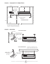
CONNECTION DIAGRAM