


4
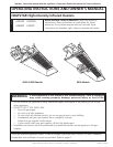
Enerco Group, Inc. |Gas-Fired Infra-Red Space Heaters OperatingInstructionsandOwner’sManual
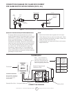
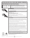
a separate regulator must be installed ahead of the
heater.RefertoFigure2formaximumallowablepres-
sure for stated model and gas.
See heater rating plate for minimum gas supply pres-
sure “For the Purpose of Input Adjustment”
On a multiple heater installation it may be possible to
use one large capacity regulator or an individual regula-
tor for each heater. Nevertheless, it is recommended
practice to make the entire pipe system a loop. Contact
your local representative or the factory for proper gas
pressure reducing design stage.
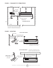
WARNING: DO NOT EXCEED ½ P.S.I. INLET PRES-
SURE TO HEATERS SHOWN IN FIGURES 1 AND 2
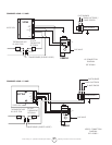
6. ELECTRICAL
Allexternalwiringmustbeinaccordancewiththe
existingelectricalcode.Usewiringdiagramfurnished
with heater. Be sure electric supply characteristics
match those called for on the name plate. The unit
must be electrically grounded in accordance with the
National Electrical Code, ANSI/NFPA70, latest revision.
In Canada refer to Canadian electrical code CSA C22.1
7. THERMOSTAT & LOCATION
Make sure that the electrical characteristics of the
thermostat match those of the heater controls. For best
results thermostat should be positioned 5 ft. above
floor where air can circulate freely around it. DO NOT
MOUNT directly to cold-side wall, in direct drafts or
directly beneath the infra-red heater.
8. VENTILATION
a.Theminimumintakeandexhaustairopeningsshallpro-
vide for not less than 400 CFM for every 100,000 BTU
inputexceptthattheinltrationareamaybeincluded
intheintakearea.Theexhaustfanmustbeinterlocked
withtheheaterthermostat.Ifapowerexhaustfan
is used, it should be controlled by the thermostat or
humidistat
b.Wherenatural(gravity)ventilationisprovidedfor
exhaust,theopeningsmustbedistributedabovethe
heaters(preferablyatthepeakoftheroof)andthe
areas of openings shall not be less than 300 square
inches for every 100,000 BTU input.
9. OPERATIONS
Upon completion of electrical wiring, gas piping and
purging of gas lines to heaters, refer to the lighting
instruction plate attached to heater for proper lighting
procedure.
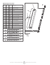
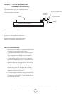
10. CLEANING INFORMATION
Blow out Venturi and burner face with compressed
air(25#max.pressure);alsocleanorices(seeFigure
2forcorrectsizedrill).Fordetailedmaintenanceand
cleaning instructions contact your local representative
or factory.
WARNING: GASKET BINDER MATERIAL USED
IN THIS HEATER ASSEMBLY WILL TEMPORARILY EMIT
ANODORAND/ORVAPOR.USEVENTILATION(aOR
b)ANDTHISCONDITIONWILLCLEARUPINAPPROXI-
MATELY 20 MINUTES AND WILL NOT REOCCUR.
WARNING: DO NOT ATTEMPT TO IGNITE THE
PILOT BY HAND ON HEATERS EQUIPPED WITH AUTO-
MATIC SPARK IGNITION.
WARNING: THE STATE OF CALIFORNIA REQUIRES
THE FOLLOWING WARNING: COMBUSTION BY-PROD-
UCTS PRODUCED WHEN USING THIS PRODUCT CON-
TAIN CARBON MONOXIDE, A CHEMICAL KNOWN TO
THE STATE OF CALIFORNIA TO CAUSE CANCER AND
BIRTHDEFECTS(OROTHERREPRODUCTIVEHARM).
NOTE: USE LATEST EDITION FOR ALL ANSI STAN-
DARD AND CANADIAN STANDARDS.
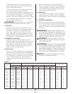
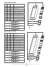
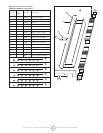
FIGURE 2
MODEL
NO.
BTU/HR. RATING GASSUPPLYPRESSURE(W.C.)
ORIFICE SIZE
GAS MIN. MAX. MANIFOLD
NATURAL PROPANE NAT. L.P. NAT. L.P. NAT. L.P. NAT. L.P.
4030 30,000 30,000 6.6” 11” 14” 14” 5.6” 10” 43 52
4040 40,000 40,000 6.8” 11” 14” 14” 5.8” 10” 37 49
8050 50,000 50,000 7.0” 11” 14” 14” 4.3” 10” 30 45
8060 60,000 60,000 7.0” 11” 14” 14” 5.8” 10” 29 43
8070 70,000 – 7.0” – 14” – 6.0” – 28 –
9080 80,000 80,000 7.0” 11” 14” 14” 5.8” 10” 37 49
9090 90,000 90,000 7.0” 11” 14” 14” 5.0” 10” 32 47
9100S 100,000 100,000 7.0” 11” 14” 14” 5.0” 10” 31 46
9100 100,000 100,000 7.0” 11” 14” 14” 4.3” 10” 30 45
9120 120,000 120,000 7.0” 11” 14” 14” 5.8” 10” 29 43
9140 140,000 – 7.0” – 14” – 5.5” – 28 –