


25741-0-0309 Page 19
Thermostats are not approved on vented decorative appliances.
Label all wires prior to disconnection when servicing controls.
Wiring errors can cause improper and dangerous operation. Verify
proper operation after servicing.
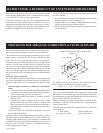
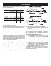
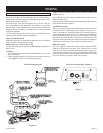
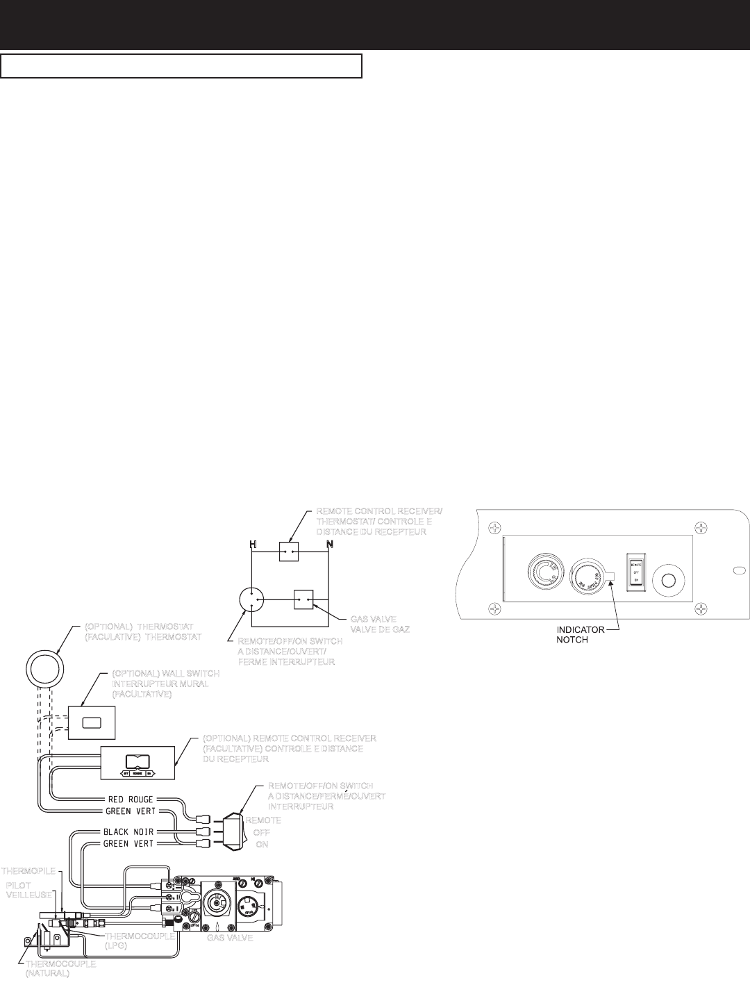
The millivolt gas valve does not require 24 or 110 volts. The gas
valve is powered by the thermopile. See Figure 16 to provide
optional wall switch, thermostat, or remote control. Maximum
length of 20 feet of 16 AWG to conductor wires is to be used with
all optional switches.
Use the red and green leads from the rocker switch that are wire
nutted together to attach optional components.
Millivolt system and all individual components may be checked
with a millivolt meter 0-1000 MV range.
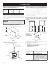
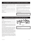
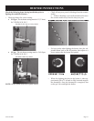
Use the following steps to place the adjacent to
the gas valve.
1. The remote receiver can not be placed behind the gas valve and
burner assembly.
2. When facing the appliance, the remote receiver must be placed
to the of the gas valve and burner assembly.
Do not let remote control receiver come in contact with
burner assembly.
behind bottom louver.
Refer to remote control installation and operating instructions for
more details on remote control.
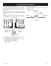
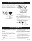
When you ignite the pilot, the thermocouple produces millivolts
(electrical current) which energizes the magnet in the gas valve.
After 30 seconds to 1 minute time period you can release the gas
operate an additional one (1) to two (2) minutes before you turn the
gas control knob from the PILOT position to the ON position. This
time period allows the millivolts (electrical current) to buildup to a
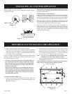
The valve regulator controls the burner pressure which should be
checked at the pressure test point. Turn captured screw counter
clockwise 2 or 3 turns and then place tubing to pressure gauge over
test point (Use test point “out” closest to control knob). After taking
to re-seal. Do not over torque. Check for gas leaks.
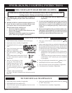
wIrING
REMOTE/OFF/ON SWITCH
ADISTANCE/FERME/OUVERT
INTERRUPTEUR
THERMOPILE
GAS VALVE
THERMOCOUPLE
(NATURAL)
OFF
ON
REMOTE
(OPTIONAL) REMOTE CONTROLRECEIVER
(FACULTATIVE) CONTROLEEDISTANCE
DU RECEPTEUR
(OPTIONAL) WALLSWITCH
INTERRUPTEUR MURAL
(FACULTATIVE)
(OPTIONAL) THERMOSTAT
(FACULATIVE) THERMOSTAT
GASVALVE
VALVEDE GAZ
REMOTE/OFF/ONSWITCH
ADISTANCE/OUVERT/
FERME INTERRUPTEUR
REMOTECONTROL RECEIVER/
THERMOSTAT/ CONTROLE E
DISTANCE DU RECEPTEUR
H N
PILOT
VEILLEUSE
THERMOCOUPLE
(LPG)