


Page 523200-0-1206
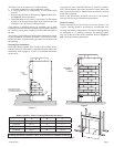
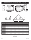
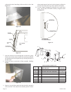
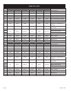
Deluxe Vent-Free Firebox Framing Dimensions (in inches)
"A" "B" "C"
Model Framing Height Framing Width Framing Depth
VFD32FB 36 1/8" 35" 17"
VFD36FB 38 1/8" 40" 19 3/8"
VFD42FB 38 1/8" 44" 19 3/8"
Attention: Add 3-3/4" to "A" Dimension when using flush mantel base.
Framing dimension A includes a three inch clearance for standoffs on firebox.
Accessory kits such as the FBB5 Blower kit, Trim kits, Mantles,
Full Cabinet Mantels, plus other Decorative Frame, Hood, and
Door accessory kits may be installed after the firebox is secured
to the framed opening.
Refer to the instructions provided with each of the optional
accessory kits for proper installation and operation.
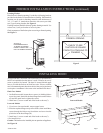
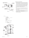
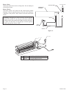
Firebox Framing
Firebox framing can be built before or after the firebox is set
in place. Framing should be positioned to accommodate wall
covering and firebox facing material. The firebox framing should
be constructed of 2 x 4 lumber or heavier. The framing headers
may rest on the top of the firebox standoffs. Refer to Figures 6
and 7 for firebox framing dimensions.
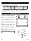
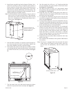
The firebox can be mounted on any of these surfaces:
1. A flat hard combustible or non-combustible surface.
2. A raised platform of combustible or non-combustible
material.
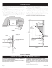
3. Recessed into the floor as illustrated by Figure 4 (flush face),
and Figure 5 (louvered models).
4. Supported under all (4) corners of the firebox so that contact
is made on all four perimeter edges on the bottom of the unit
(Example: Four (4) concrete masonry blocks).
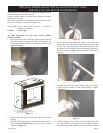
If the firebox is installed directly on carpeting, tile or other
combustible material other than wood flooring, it should be installed
on a metal or wood panel extending the full width and depth of
the unit.
At this point, you should have decided what components to include
in your installation, and where the firebox is to be located. If this
has not been done, stop and consult your dealer for assistance
with
this planning.
Planning Your Installation
Please note that the optional BVA1 Fresh Air kit available for use
with the Vent Free Firebox must be installed at the time of the initial
installation. Refer to pages 9, 10, and 11 for detailed instructions
for the air kit.
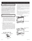
COMBUSTIBLE MATERIALSALLOWED
NON-COMBUSTIBLE
FINISHING MATERIAL
TO FIREBOX OPENING
FLUSH
FACE
MODELS
LOUVERED
FIREBOX
MODELS
COMBUSTIBLE MATERIALS ALLOWED
Figure 4
Figure 5
Figure 6