


23200-0-1206Page 10
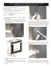
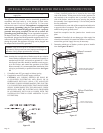
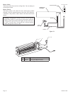
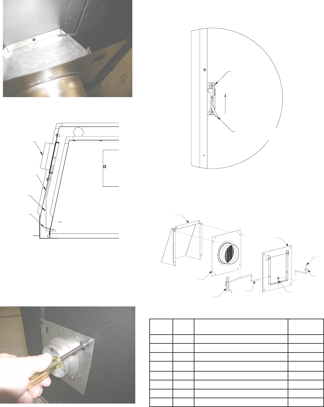
with the hole in the front flange of the movable air door. See
Figure 18.
7. Once the control rod is fed through the air door hole, gently
lift the outer air door plate assembly inward and upward until
the mounting holes in the plate line up with the pilot holes in
the side wrap.
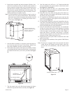
8. Install (4) screws to retain the Air Door assembly. See Fig-
ure 20.
9. Remove vise grip from control rod, then check the operation
of the Air Door. The control lever should open the air door
Figure 18
Figure 21
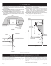
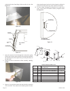
OUTSIDE AIR
ROD BRACKET
OPEN
FRESH AIR ROD
(CONTROL LEVER)
LEFT SIDE VIEW
OF FIREBOX OPENING
TO
P CUTAWAY
VIEW
DAMPER
ASSEMBL
Y
OUTER
CASING
FRESH
AIR
ROD
OUTSIDE
AIR
ROD
BRACKET
Figure 20
OUTSIDE AIR
ROD BRACKET
OPEN
FRESH AIR ROD
(CONTROL LEVER)
LEFT SIDE VIEW
OF FIREBOX OPENING
TO
P CUTAWAY
VIEW
DAMPER
ASSEMBL
Y
OUTER
CASING
FRESH
AIR
ROD
OUTSIDE
AIR
ROD
BRACKET
when rotated upward, and can be locked open by pulling for-
ward into the notch at the top of the control lever bracket.
10. To close, simply disengage by letting the lever rotate down-
ward. The air door will remain closed by magnetic action.
See Figure 21.
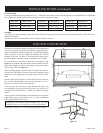
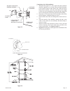
Figure 19
1
2
8
4
7
6
5
3
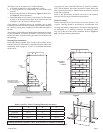
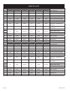
FRESH AIR KIT PARTS LIST
INDEX
NO.
PART
NO. DESCRIPTION
QUANTITY
SUPPLIED
1 10124 OUTSIDE AIR HOOD 1
2 18476 OUTSIDE AIR TUBE ASSEMBLY 1
3 R8196 WASHER, SILICONE (BV) 1
4 19548 DAMPER ASSEMBLY 1
5 R8047 TUBULAR CLIP (BV) 1
6 R8189 ROD, FRESH AIR (BV) 1
7 R8703 ROD, AIR CONTROL (FB) 1
8 20473 BRACKET, OUTSIDE AIR ROD (FB) 1