


Page 18 14008-0-0403
WIRING
Label all wires prior to disconnection when servicing controls.
Wiring errors can cause improper and dangerous operation. Verify
proper operation after servicing.
16", 18", 24" and 30" Gas Logs (Millivolt) thermopile is self
powered gas valve and does not require 110 volts. See Figure 21
to provide optional wall switch, thermostat, or remote control.
Maximum length of 20 feet of 16 AWG to conductor wires is to
be used with all optional switches.
Use the two leads (black wires) from ON/OFF switch to attach
optional components.
Check System Operation
Millivolt system and all individual components may be checked
with a millivolt meter 0-1000 MV range.
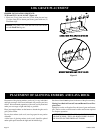
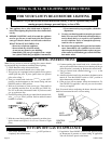
Remote Receiver -VFSR-(16, 18, 24, 30)
Use the following steps to place the remote receiver adjacent to
the gas valve.
Attention:
1. The remote receiver can not be placed behind the gas valve
and burner assembly.
2. When facing the appliance, the remote receiver must be placed
in the right side of firebox, toward the front.
Note: Do not let remote control receiver come in contact with
burner assembly.
On circulating vent-free firebox, install remote control receiver
behind bottom louver.
Refer to remote control installation and operating instructions for
more details on remote control.
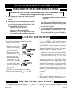
750 Millivolt System
When you ignite the pilot, the thermocouple produces millivolts
(electrical current) which energizes the magnet in the gas valve.
After 30 seconds to 1 minute time period you can release the gas
control knob and the pilot will stay ON. Allow your pilot flame
to operate an additional one (1) to two (2) minutes before you turn
the gas control knob from the PILOT position to the ON position.
This time period allows the millivolts (electrical current) to
buildup to a sufficient level allowing the gas control to operate
properly.
Millivolt Control
The valve regulator controls the burner pressure which should
be checked at the pressure test point. Turn captured screw counter
clockwise 2 or 3 turns and then place tubing to pressure gauge
over test point (Use test point “A” closest to control knob). After
taking pressure reading, be sure and turn captured screw
clockwise firmly to re-seal. Do not over torque. Check for gas
leaks.
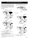
VFSR
Note: (Wiring harness located in envelope)
Connect the 2 - 1/4" terminals onto the TH and TH/TP terminals
on valve. Place decorative log or switch bracket (switch bracket
is used with Flame Art log sets) to right of the gas valve and
burner assembly. When connecting to remote receiver, cut off 1/
4" terminals from wires attached to ON/OFF switch. Strip wires
back about 1/4". Connect stripped ends into remote receiver.
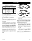
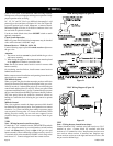
VFSR Wiring Diagram (Figure 21)
Figure 21
VFSV Wiring Diagram (Figure 22)
Figure 22
VFSV
Note: (Wiring harness located in envelope)
Connect black/red 3/16" terminal wire from receiver to 3/16"
terminal on valve. Connect black 1/4" terminal wire from
receiver to 1/4" terminal on valve. Install remote receiver cover
over receiver when receiver is installed into fireplace area.
Locate receiver and cover to the right and forward of valve. (Do
not put receiver behind logs)