


Page 8
VENT SAFETY SHUTOFF SYSTEM
This heater must be properly connected to a venting system. This
heater is equipped with a vent safety shutoff system.
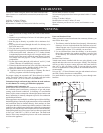
This appliance needs fresh air for safe operation and must be
installed so there are provisions for adequate combustion and
ventilation air.
This room heater is equipped with a vent safety switch. The vent
safety switch will cause gas flow to the pilot to “shut off” due to
improper venting or a blocked flue.
If the vent safety switch continues to “shut off” the gas flow to
the pilot, a qualified service person must be contacted to inspect
for improper venting, blockage in the vent pipe or the vent safety
switch for being defective.
Warning:
Operation of this heater, when not connected to a
properly installed and maintained venting system or
tampering with the vent safety shutoff system, can result in
carbon monoxide (CO) poisoning and possible death.
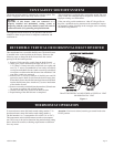
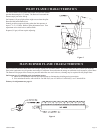
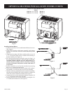
REVERSIBLE VERTICAL OR HORIZONTAL DRAFT DIVERTER
This room heater has a reversible draft diverter. The draft diverter
is installed in the vertical position at the factory. Please use the
following steps to change the draft diverter from the vertical
positing to the horizontal position.
1. Remove L280 vent safety switch from the draft diverter.
2. Inside your yellow instruction envelope will be a 1 1/2” x 2
1/4” (38mm x 51mm) vent safety switch hole cover plate and
two (2) 1/2” screws for attachment of vent safety switch hole
cover plate to the draft diverter. Attach vent safety switch hole
cover plate over hole on the draft diverter from which the L280
vent safety switch was removed.
3. Remove two (2) screws at bottom of draft diverter and lift
upward to remove draft diverter from the draft diverter plate.
Rotate draft diverter into the horizontal position and slide back
into the draft diverter plate. Attach two (2) screws into bottom
of the drafter diverter.
4. Remove vent safety switch hole knockout and two (2) knockouts
for screws on opposite side of draft diverter.
5. Attach L280 vent safety switch to the draft diverter.
6. Repositioning of the draft diverter is completed.
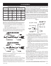
DRAFT DIVERTER CAN BE EITHER A VERTICAL VENT
OR HORIZONTAL VENT
Figure 4
THERMOSTAT OPERATION
To turn on burner, rotate dial knob toward setting number 7. To
shut down burner, rotate dial knob toward setting number 1.
The dial numbers 1 to 7 correspond to 50
o
to 90
o
F (10
o
to 32
o
C).
This temperature at the bulb thermostat, not the room tempera-
ture. The owner is advised to determine the particular heat setting
that is desired for comfort, as heating requirements are different
for every owner.
Attention: If no heat is desired, turn the gas control knob to the
PILOT position.
12822-4-0806