


Page 17
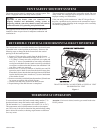
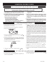
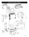
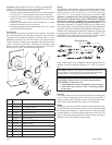
Attention: Wiring harness on blower is factory assembled and
installed. If wiring harness becomes disassembled, use the fol-
lowing steps to reassemble the wiring harness.
1. Attach (1) pin terminal from black (hot) wire, smooth insulation
on cord set to (1) socket terminal on fan control assembly.
2. Attach (1) pin terminal from black (neutral) wire, ribbed insu
-
lation on cord set to (1) socket terminal from white (neutral)
wire on motor.
3. Attach (1) pin terminal on fan control assembly to (1) socket
terminal from black (hot) wire on motor.
4. Attach green ground wire beneath one of the #10 x 1/2” (13mm)
screws on the blower housing.
Fan Control
The automatic fan control is located in the switch box. The switch
box is attached to the front of the blower assembly. The switch box
is adjacent to the combustion chamber. The fan control is a non-
adjustable automatic type. The fan control will require between
5 and 10 minutes of main burner operation before the fan control
“closes” and activates the blower. The blower will continue to run
between 5 and 10 minutes after the main burner shuts off, before
the fan control “opens” and deactivates the blower.
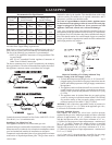
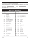
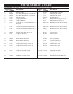
Index
No.
Part
No.
Description
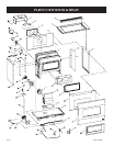
1 11727 Blower Housing and Chute Assembly
2 9120106 Fan Control Switch
3 RH-863 Switch Box
4 DV-807 Switch Box Cover
5 R-2091 Wire Assembly
6 642031 Blower Wheel
7 11728 Motor Mounting Plate
8 632016 Motor Cushion
9 R-2605 Motor
10 8720161 Strain Relief Bushing
11 R-2099 Cord Set
12 RH-138 Blower Cushion
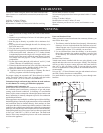
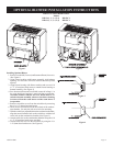
Wiring
The appliance, when installed, must be electrically grounded in ac
-
cordance with local codes or, in the absence of local codes, with the
National Electrical Code, ANSI/NFPA 70 or Canadian Electrical
Code, CSA C22.1, if an external electrical source is utilized.
This
appliance is equipped with a three-prong [grounding] plug for
your protection against shock hazard and should be plugged
directly into a properly grounded three-prong receptacle. Do
not cut or remove the grounding prong from this plug. For an
ungrounded receptacle, an adapter, which has two prongs and a
wire for grounding, can be purchased, plugged into the ungrounded
receptacle and its wire connected to the receptacle mounting screws.
With this wire completing the ground, the appliance cord plug can
be plugged into the adapter and be electrically grounded. A 7/8”
(22mm) hole is provided in the junction box for use with a conduit
connector if local codes require this type of protection.
Wiring Diagram
If any of the original wire as supplied with the appliance must be
replaced, it must be replaced with type 125
o
C wire or its equiva-
lent.
Cleaning
The blower wheel will collect lint and could require cleaning once
a year. If the air output decreases or the noise level increases, it
indicates a dirty wheel. Complete removal of the wheel and scrub
-
bing it with a brush under flowing water is recommended.
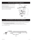
Oiling
The blower motor has an oil hole located on each end of the motor.
Use #20 motor oil only. It is best to oil the motor several times during
the heating season using 2 or 3 drops each time. If the motor fails
to start and hums, it could be a tight bearing due to lack of oil. This
may be corrected by pouring kerosene in the oil holes, allowing to
stand for a few hours and then oiling properly.
CAUTION: Label all wires prior to disconnection when ser-
vicing controls. Wiring errors can cause improper and danger
-
ous operation. Verify proper operation after servicing.
Warning:
Unplugging of blower accessory will not stop the heater
from cycling. To shut heater off:
1. Turn temperature dial or thermostat to lowest setting.
2. Turn knob n gas control to “OFF,” depressing slightly.
Do not force.
12822-4-0806