


Page 919400-3-0406
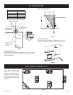
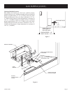
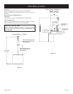
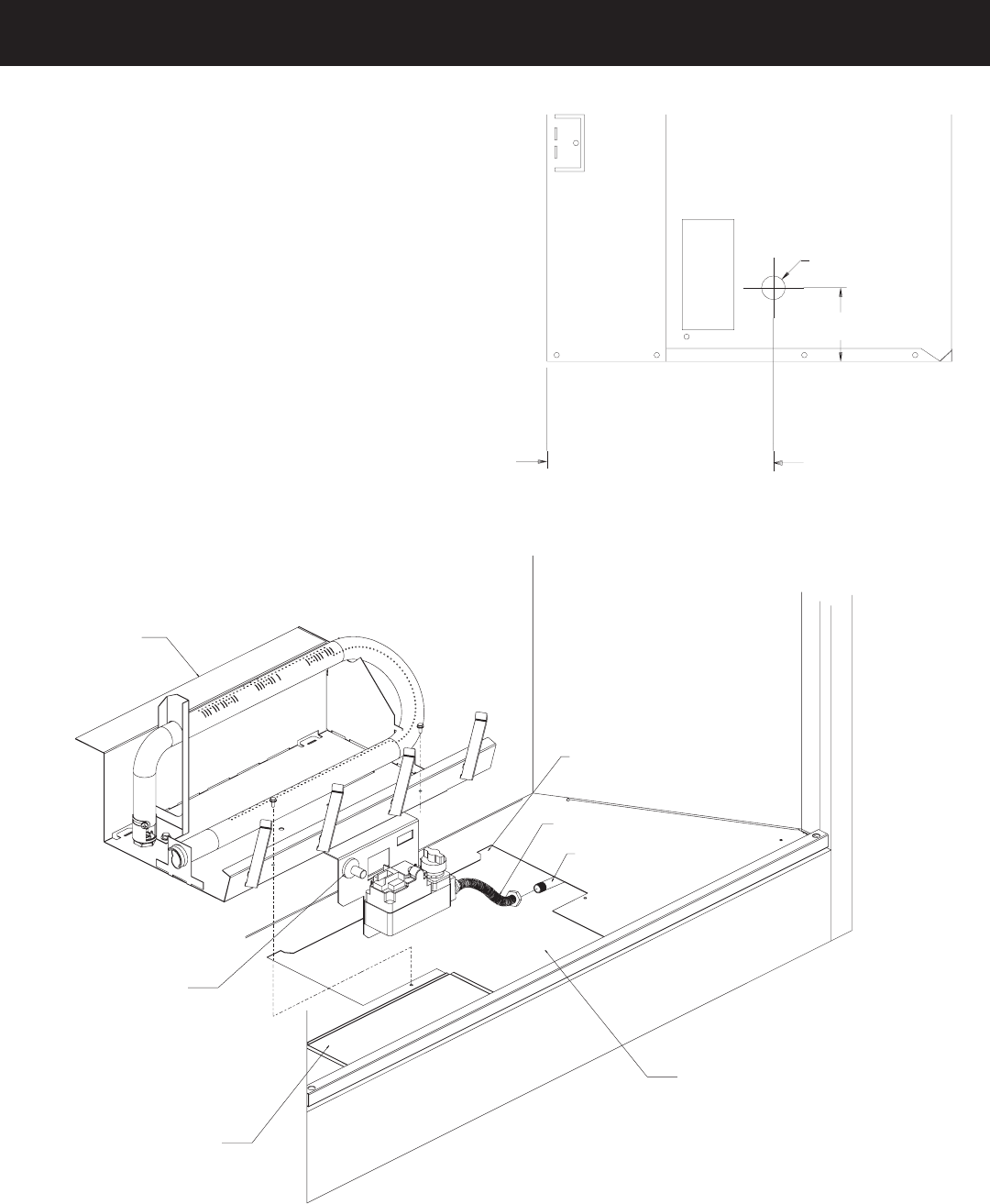
FROM FRONT OF
APPLIANCE TO
GAS LINE HOLE
3 ½”
GAS LINE HOLE
BVD34 SERIES - 10”
BVD,P (36,42) - 13 ½”
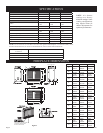
Figure 7
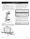
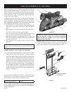
BURNER ASSEMBLY
REAR TA
B (BURNER BASE)
LOCATIONS
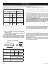
FLEXIBLE GAS CONNECTOR
GAS SUPPL
Y LINE
FIREBOX BOTTOM
CUTOUTACCESS
SLIDING
VALV
EACCESS
COVER
PIEZO
IGNITER
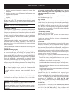
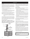
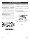
Checking Manifold Pressures
Both Propane and Natural gas valves have a built-in pressure
regulator in the gas valve. Natural gas models will have a manifold
pressure of approximately 3.5" w.c. (.871kPa) at the valve outlet
with the inlet pressure to the valve from a minimum of 4.5" w.c.
(1.120kPa) for the purpose of input adjustment to a maximum of
14.0" w.c. (3.484kPa). Propane gas models will have a manifold
pressure approximately 10.0" w.c. (2.49kPa) at the valve outlet
with the inlet pressure to the valve from a minimum of 10.8" w.c.
(2.68kPa) for the purpose of input adjustment to a maximum of
14.0" w.c. (3.484kPa).
Figure 8
GAS SUPPLY (CONT)