


Page 1719400-3-0406
STANDING PILOT OPERATING INSTRUCTIONS
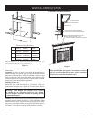
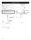
The fireplace is equipped with a 15 foot length of wire that can
be used to connect the valve to a wall switch (installer provided)
or remote control receiver.
See instructions packed with each of the following optional switches
or controls for proper installation, operation, and maintenance.
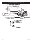
Wall Switch, FWS-1 (optional)
On millivolt valve models, a 15' wall switch wire is included.
Connect the two leads to a wall switch (installer supplied). See
Figure 23.
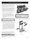
FRBC Battery Operated Remote Control
To connect the FRBC remote to the millivolt gas valve on your
"B-Vent" Fireplace, disconnect one wire terminal lead (wall
switch wire) from gas valve, seperate/split wall switch wire lead
approximately 18 inches. Cut the removed lead 12 inches long
and strip both cut ends. After stripping and baring the wire ends,
connect the two stripped ends to the remote receiver. Reconnect
the 1/4" insulated wire terminal (short 18" wire) to the gas valve
wire terminal. See Figure 23.
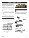
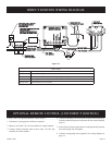
Electric (120 volt) Operated Remote Control, FREC
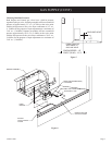
Installation of the 120 Volt Receiver
Note: If you have a louvered model fireplace and will be installing
the blower option, the fireplace junction box receptacle should be
wired in accordance with Figure 28 for proper independent operation
of the FREC remote and the optional FBB4 Blower kit.
To connect the FREC Remote to the millivolt gas valve on your
"B"-Vent fireplace, disconnect both of the insulated wall switch
wire terminal leads from the gas valve and discard the wall switch
wire. Connect the two wire leads from the FREC receiver to the
TH and TH/TP terminals on the gas valve.
Next, attach the short power cord to the remote receiver, then
plug the power cord into the junction box receptacle located at
the bottom right side of the fireplace.
The remote receiver should be located on the floor of the fireplace
to the right of the gas valve.
Attention: The Velcro loop and hook are not necessary in this
installation but can be used to secure remote receiver.
Refer to remote control installation and operating instructions for
more details on remote control.
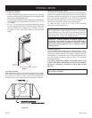
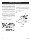
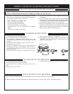
Millivolt Control
The valve regulator controls the burner pressure which should be
checked at the pressure test point. Turn captured screw counter
clockwise 2 or 3 turns and then place tubing to pressure gauge over
test point (Use test point “A” closest to control knob). After taking
pressure reading, be sure and turn captured screw clockwise firmly
to re-seal. Do not over torque. Check for gas leaks.
Millivolt thermopile is self generating. Gas valve does not require
24 volts or 110 volts.
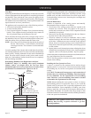
Check System Operation
Millivolt system and all individual components may be checked
with a millivolt meter 0-1000 MV range.
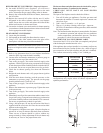
It is important to use wire of a gauge proper for the length of the
wire:
Recommended Wire Gauges
Maximum Length Wire Gauge
1' to 10' 18
10' to 25' 16
25' to 35' 14
CAUTION: Disconnect all electrical supply to the fireplace
prior to installing the remote control optional equipment.
OPERATING INSTRUCTIONS (CONT)