


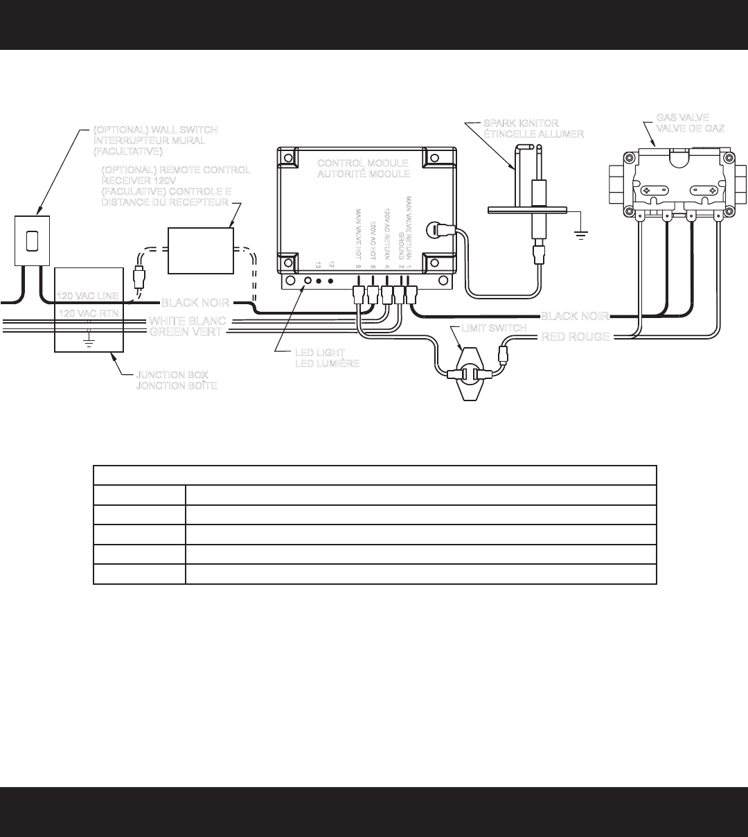
Page 2319400-3-0406
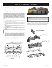
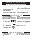
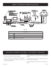
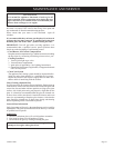
LED LIGHT
LED LUMIÈRE
BLACK NOIR
GREEN VERT
WHITE BLANC
RED ROUGE
BLACK NOIR
GAS VALVE
VALVE D
E GAZ
(OPTIONAL) WALL SWITCH
INTERRUPTEUR MURAL
(FACULTATIVE)
120 VAC LINE
120 VAC RTN
JUNCTION BOX
JONCTION BOÎTE
SPARK IGNITOR
ÉTINCELLEALLUMER
(OPTIONAL) REMOTE CONTROL
RECEIVER 120V
(FACULATIVE) CONTROLE E
DISTANCE DU RECEPTEUR
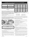
MAI
NV
AL
VE
RETURN
1
12
13
GROUND
2
120V
AC
RETURN
4
120V
AC
HOT
6
MAI
NV
AL
VE
HOT
8
CONTROLMODULE
AUTORITÉ MODULE
LIMIT SWITCH
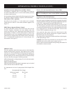
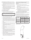
LED CODES
Steady ON Normal operation, power ON to control
2 Flashes 3 unsuccessful ignition trials
3 Flashes Main burner flame failed 4 times during a single heating cycle
4 Flashes Interrupt power for 5 seconds to reset control
Steady Flash Flame detected out of sequence
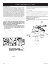
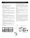
Electric (120 volt) Operated Remote Control (FREC)
1. Disconnect 3-prong power cord from receptacle.
2. Remove wire from 120 VAC hot terminal on control module.
3. Connect female terminal from receiver onto 120 VAC hot
terminal on control module.
4. Connect remaining wire from remote control (male terminal) to
(female terminal) on power cord removed from control module
(step 2).
5. Insert electric remote control power cord plug into the junction
box on the right side of fireplace.
6. Connect 3-prong plug into receptacle. See wiring diagram on
page 34.
Figure 24
DIRECT IGNITION WIRING DIAGRAM
OPTIONAL REMOTE CONTROL (120V DIRECT IGNITION)