


25613-0-0309 Page 27
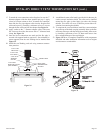
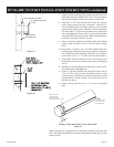
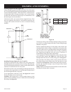
7. Remove outside mounting plate with tube attached from wall.
Mark and cut the extra length of the 6 5/8” (168 mm) diameter
tube from the opposite end. Do not crimp or enlarge tube.
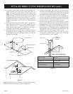
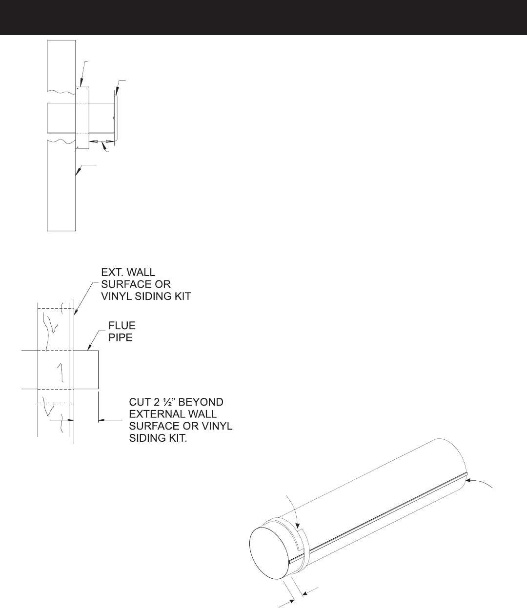
8. Attach the 4” (102 mm) diameter ue outlet tube onto the
rigid venting system or directly to replace. Ensure the 4”
(102 mm) diameter ue outlet tube is placed as far as possible
onto the rigid venting system. Mark the 4” (102 mm) diameter
ue outlet tube 2 1/2” (64 mm) beyond the vinyl siding kit or
wall. See Figure 39. Remove the 4” (102 mm) diameter ue
outlet tube from rigid venting system. When installing directly
to replace, tape gasket needs to be used.
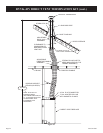
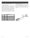
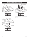
9. Mark or wrap tape completely around the tubes at the marked
points to help in making a true cut. Do not crimp or enlarge
tubes.
10. From outside: Push the 6 5/8” (168 mm) diameter inlet tube/
mounting plate onto end of rigid venting system to correct posi-
tion. Fasten the outside mounting plate to the vinyl siding kit
or wall with (4) 10 x 1 1/2” screws. (Ensure upward slope).
11. From inside: Attach the inlet tube to the collar on the back of
the replace (or the rigid venting system) using (3) self tapping
screws.
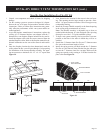
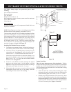
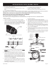
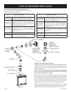
12. Seal the 4” (102 mm) diameter ue outlet tube. Follow instruc-
tions and diagram. See Figure 41.
13. Fasten 4” (102 mm) diameter ue outlet tube in place. Do not
“twist” the ue outlet tube into the replace collar (or rigid
venting system). Hold the tube by the seam and push in using
a perpendicular “rocking” motion. This ensures the seam on
the tube stay intact.
14. Fasten vent cap end using (3) 10 x 1/2” screws to mounting
plate.
OUTSIDE WALL
MEASURE
VINYL SIDING KIT DV822
OUTSIDE MOUNTING
PLATE
Figure 39
Figure 40
1
”
VENT CAP END
APPLYSEALANT
ON THE INSIDE
DO NOT PLACE
OVERLAPPED
SECTION OVER
THE SEAMIN THE TUBE
Sealing 4” (102 mm) Diameter Flue Outlet Tube.
Figure 41
Note: Tape gasket to be applied prior to installing to replace ue outlet tube
only. Tape gasket should not be used when mating the ue outlet tube to a rigid
venting system.
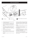
DVVK-4RE VENT KIT INSTALLATION INSTRUCTIONS (continued)