


25613-0-0309Page 22
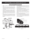
10. With the ex vent assembly and the 48” long hard pipe com-
ponents laid out on the oor, begin securing these parts to-
gether. First, apply a generous bead of silicone sealant to the
inside of the 4” diameter ex ue (not the end with the pre-
installed connector), then slide the ex ue over the 4” diam-
eter hard pipe ue. Be sure to overlap at least 1-1/4”. Secure
this connection with a 4” diameter band clamp provided. Be
careful not to damage or tear the ex ue when tightening
clamp.
11. Repeat the connection process for the outer 7” diameter ex
vent to hard pipe connection. Use silicone sealant at this joint
also, overlap at least 1-1/4”, then secure the joint with the 7”
diameter band clamp provided. Be careful not to damage or
tear the ex vent pipe when tightening the clamp.
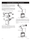
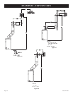
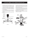
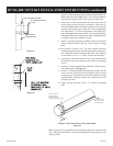
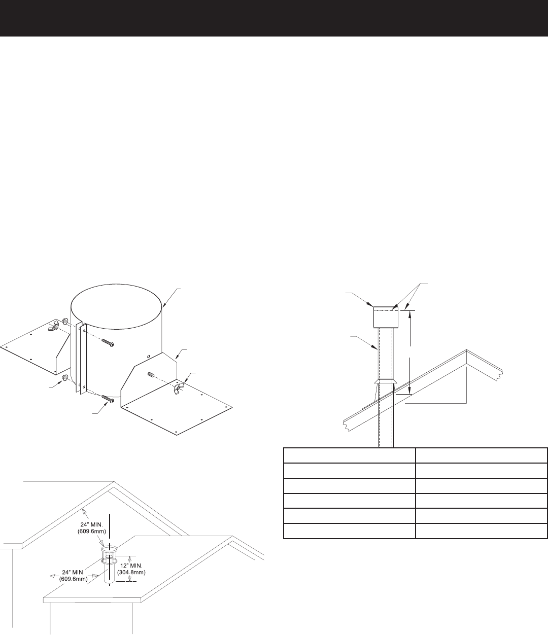
12. While the venting is still on the oor, assemble the roof jack
components as shown in Figure 31 and pre-install the roof
jack assembly to the hard pipe approximately 18” from the
top end of the hard pipe.
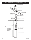
13. Now the pre-assembled vent system may be carried to the
roof, then lowered through the roof cutout opening (see step
5). Feed the ex vent end down through the roof opening and
restop/thimble assembly installed in steps 4 through 6.
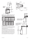
14. Secure the roof support assembly to the roof sheathing with
at least (4) nails/screws through each support bracket. Check
that the combustible clearances through the roof framing will
maintain at least a 1” clearance from the vent pipe.
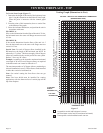
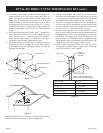
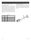
15. Determine how high the vent terminal should be located
above the roof line based on the roof pitch information shown
in Figure 33. Adjust the vent system height by loosening the
pre-installed roof support pipe clamp and sliding the vent
pipe up or down as pre-determined, then re-tighten the pipe
clamp. Install a couple of sheet metal screws through the pipe
clamp into the outer hard vent pipe to lock in place.
16. Check to make sure that the bottom end of the ex vent is
long enough to reach the replace adapter collars. If too long,
trim off the extra ex vent not needed.
NUT (2)
SCREW (2)
PIPE CLAMP
ROOF BRACKET (2)
WING NUT (2)
H
X
12
VENTCAP
GAS VENT
LOWEST
DISCHARGE
OPENING
ROOF PITCHIS X/12
H(Min.)-Minimum height from
roof to lowest discharge opening
Figure 31
Figure 33
ROOF PITCH H (Min.)
Flat to 6/12 12” (305 mm)
6/12 to 7/12 15” (381 mm)
Over 7/12 to 8/12 18” (457 mm)
Over 8/12 to 16/12 24” (610 mm)
Over 16/12 to 21/12 36” (914 mm)
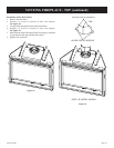
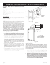
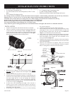
DVVK-4FV DIRECT VENT TERMINATION KIT (cont.)
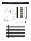
Figure 32
When terminating the vent cap near an exterior wall or overhang,
maintain minimum clearances as shown in Figure 32.