


25613-0-0309Page 12
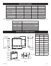
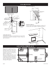
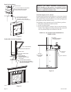
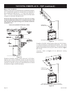
Flush Wall Installation
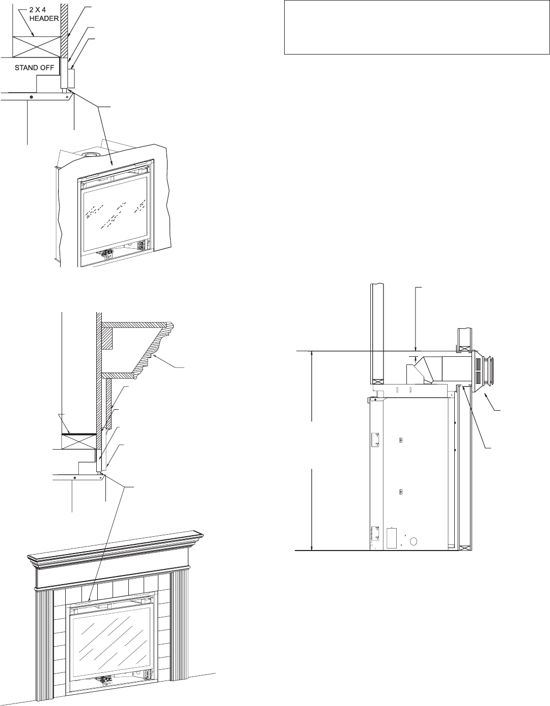
Figure 12
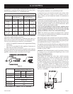
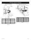
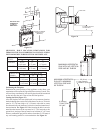
Combustible Surround Installation
Figure 13
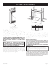
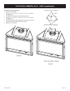
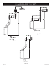
Vent Runs (Figures 14, 15, and 16)
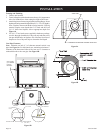
In planning the installation for the replace, it is necessary to install
certain components before the appliance is completely positioned
and installed. These include the direct vent system, gas piping for
the appliance and the electrical wiring.
The appliance can be mounted on any of the following surfaces:
1. A at, hard combustible (burnable) surface.
2. A raised wooden platform.
3. Four (4) corner supports. (Example: Four (4) concrete masonry
blocks.) These supports must be positioned so they contact all
four (4) perimeter edges on the bottom of the unit.
VERTICAL, 90° ELBOW WITH HORIZONTAL
TERMINATION
Figure 14
FINISHED WALL
JOINT BETWEEN FINISHED
WALL AND UNITSEALED
WITH 300° F, 149°CSEALANT
MATERIAL(SEALANTISOPTIONAL)
6” OF NON-COMBUSTIBLE MATERIAL
NON-COMBUSTIBLE MATERIAL
(INSTALLATION IS OPTIONAL
FINISHED WALL
COMBUSTIBLE SURROUND
MANTELSHELF
2X4
HEADER
STAND OFF
6” OF NON-COMBUSTIBLE
MATERIAL
FRONT TRIM OR
NON-COMBUSTIBLE
MATERIAL (INSTALLATION
IS OPTIONAL)
JOINT BETWEEN FINISHED
WALLAND UNIT SEALED WITH
300°F (149°C) SEALANT MATERIAL
(SEALANT IS OPTIONAL)
Attention: Cold climate installation recommendation:
When installing this unit against a non-insulated exterior
wall, it is recommended that the outer walls be insulated to
conform to applicable insulation codes.
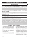
3” (76mm)
MINIMUM CLEARANCE
TO COMBUSTIBLES
VENT CAP/
THIMBLE
WALL FIRESTOP
DVX36,42
50 1/2” (1283mm)
TO BOTTOM
OF UNIT