


25613-0-0309 Page 21
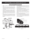
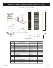
1. Unpack vent components and check all items for shipping
damage.
2. For this venting system to operate as designed it is depen-
dent on the use of all parts and procedures detailed in these
instructions. Failure to follow these instructions may poten-
tially affect the performance of this vent system and the at-
tached appliance.
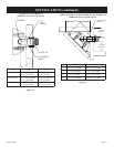
3. As per the replace manufacturer’s instructions, replace the
existing 6 5/8” diameter replace vent adapter with the 7”
diameter ex vent replace adapter included in the vent kit.
Install the adapter collar with the screws removed from the
standard replace collar. Refer to the replace manual for ad-
ditional information on the vent collar removal and installa-
tion.
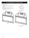
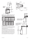
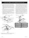
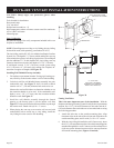
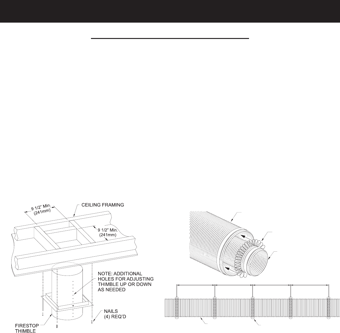
4. Once the replace location has been determined, mark the
ceiling where the ex vent will pass through. Cut an opening
for installation of the restop thimble assembly. The open-
ing must measure a minimum of 9-1/2” x 9-1/2” square. See
Figure 29.
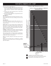
5. Next, determine the location for the cutout in the roof open-
ing. This opening must be large enough to provide a mini-
mum 1” air space clearance from the vertical vent pipe to any
combustible framing.
6. Install the Firestop/Thimble assembly to the framed opening
in the ceiling using common nails or screws.
Note: The thimble assembly is adjustable up or down as
needed within the restop. It is also designed with a pivoting
restop for use with 0 - 3/12 pitch cathedral ceilings.
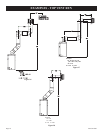
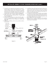
7. To begin vent system assembly, rst layout all the vent com-
ponents on the oor in the order in which they will be as-
sembled.
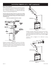
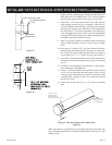
8. Stretch the 4” diameter inner ex ue and 7” diameter outer
ex vent to the maximum length of 6 feet.
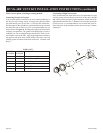
9. Install the spring spacers provided around the 4” diameter
ex ue at 1 foot intervals, then slide the ue pipe with spac-
ers into the 7” diameter outer ex vent pipe. Make sure the
springs are spaced evenly starting at 12 inches from the re-
place collar. See Figure 30.
FLEX OUTER
AIR INTAKE PIPE
SPACER SPRINGS
FLEX FLUE PIPE
Figure 29
Figure 30
305mm 305mm 305mm 305mm
12”12” 12”12”
4” FLEX
VENT PIPE
SPACER SPRINS
Step-By-Step Installation For Flex DV Kit
DVVK-4FV DIRECT VENT TERMINATION KIT (cont.)