


25613-0-0309 Page 11
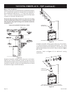
Figure 11
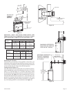
Attention: If a base is not used and the appliance is installed directly
on tile or other combustible material other than wood ooring, it
shall be installed on a metal or wood panel extending the full width
and depth of the appliance. The vertical dimension in Figure 11
must be adjusted when a metal or wood panel is placed beneath
the appliance.
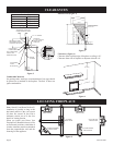
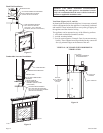
Finishing (Figures 12 and 13)
Finish the walls with the material of your choice. Figure 3 on
page 8 shows the minimum vertical and corresponding maximum
horizontal dimensions of mantels or other combustible projections
above the top front edge of the replace.
The black replace front must not be covered. It must be ush
to the nished wall.
Warning: When nishing the replace never obstruct or
modify the air inlet/outlet louvers in any manner. Provide
adequate clearances around air openings into the combustion
chamber.
Caution: If the joints between the nished wall and the replace
surround (top and sides) are sealed, a 300°F minimum sealant
material must be used. These joints are not required to be sealed.
Only non-combustible material (using 300°F minimum adhesive
if needed), can be applied as facing to the replace.
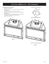
Figure 10
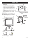
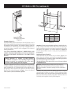
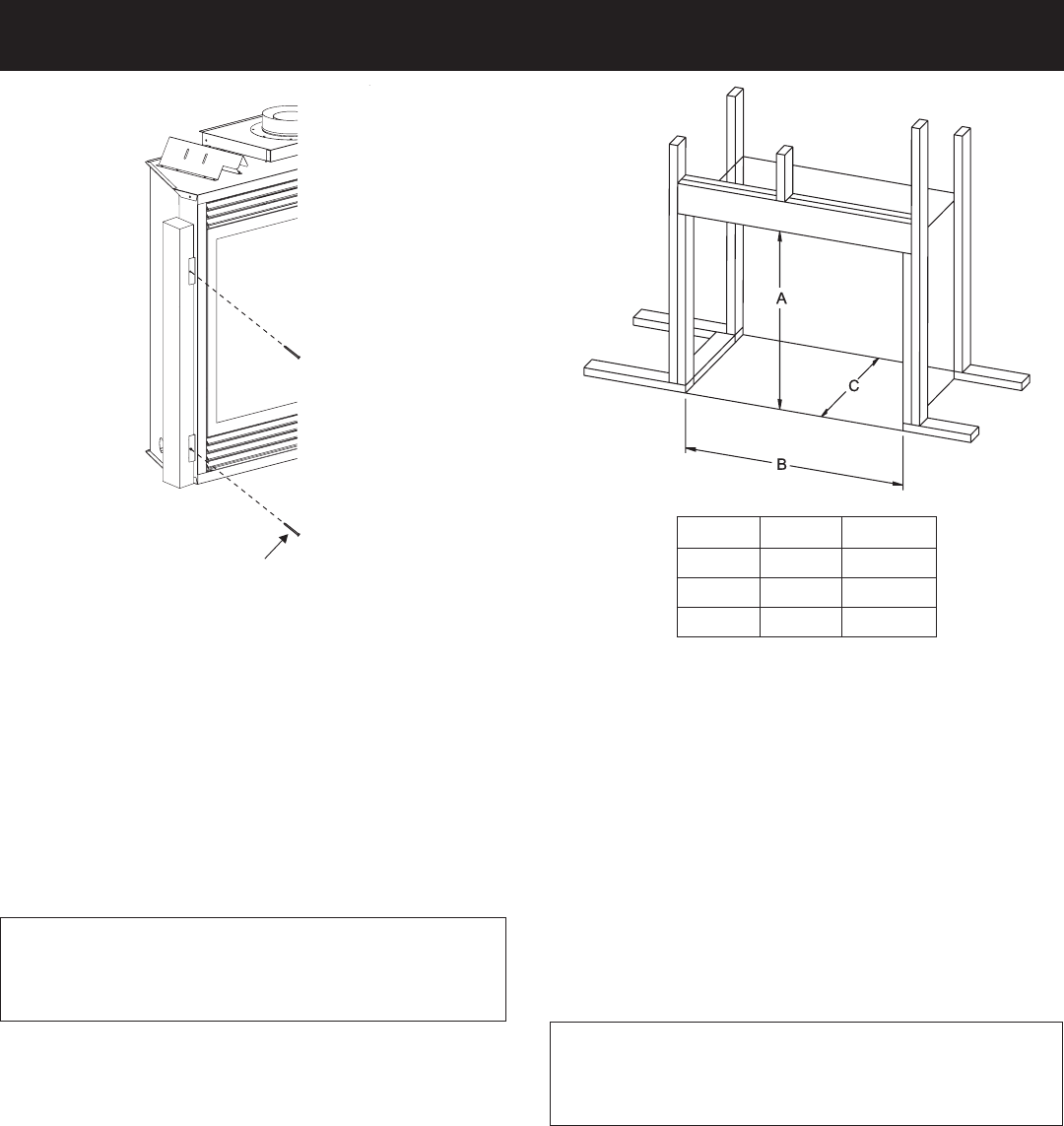
Framing (Figure 11)
Fireplace framing can be built before or after the replace is set in
place. Framing should be positioned to accommodate wall covering
and replace facing material. The replace framing should be
constructed of 2 x 4 lumber or heavier. The framing headers may
rest on the replace standoffs. Refer to Figure 11 for minimum
framing dimensions.
CAUTION: MEASURE FIREPLACE DIMENSIONS AND
VERIFY FRAMING METHODS, AND WALL COVERING
DETAILS BEFORE FRAMING CONSTRUCTION
BEGINS.
Framing dimension "A" includes a six inch clearance
for standoffs on replace. After installing replace into
framing, the nished non-combustible wall surface must
cover the six inch opening above the replace.
Attention: Appliance must not be recessed below any ooring,
including carpeting, for proper front mounting. A metal or wood
panel extending the full width and depth of the appliance may
be required to raise the unit to the same level, or above existing
ooring. The vertical dimension in Figure 11 must be adjusted
when a panel is placed beneath the appliance.
NAIL OR OTHER
SUITABLE FASTENER
INSTALLATION (continued)
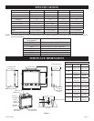
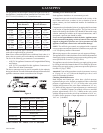
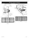
DVX36 DVX42
"A" 40 7/8" 40 7/8"
"B" 40 3/8" 43 3/8"
"C" 19 7/8" 19 7/8"