


25613-0-0309 Page 17
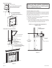
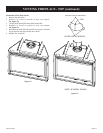
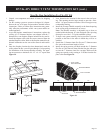
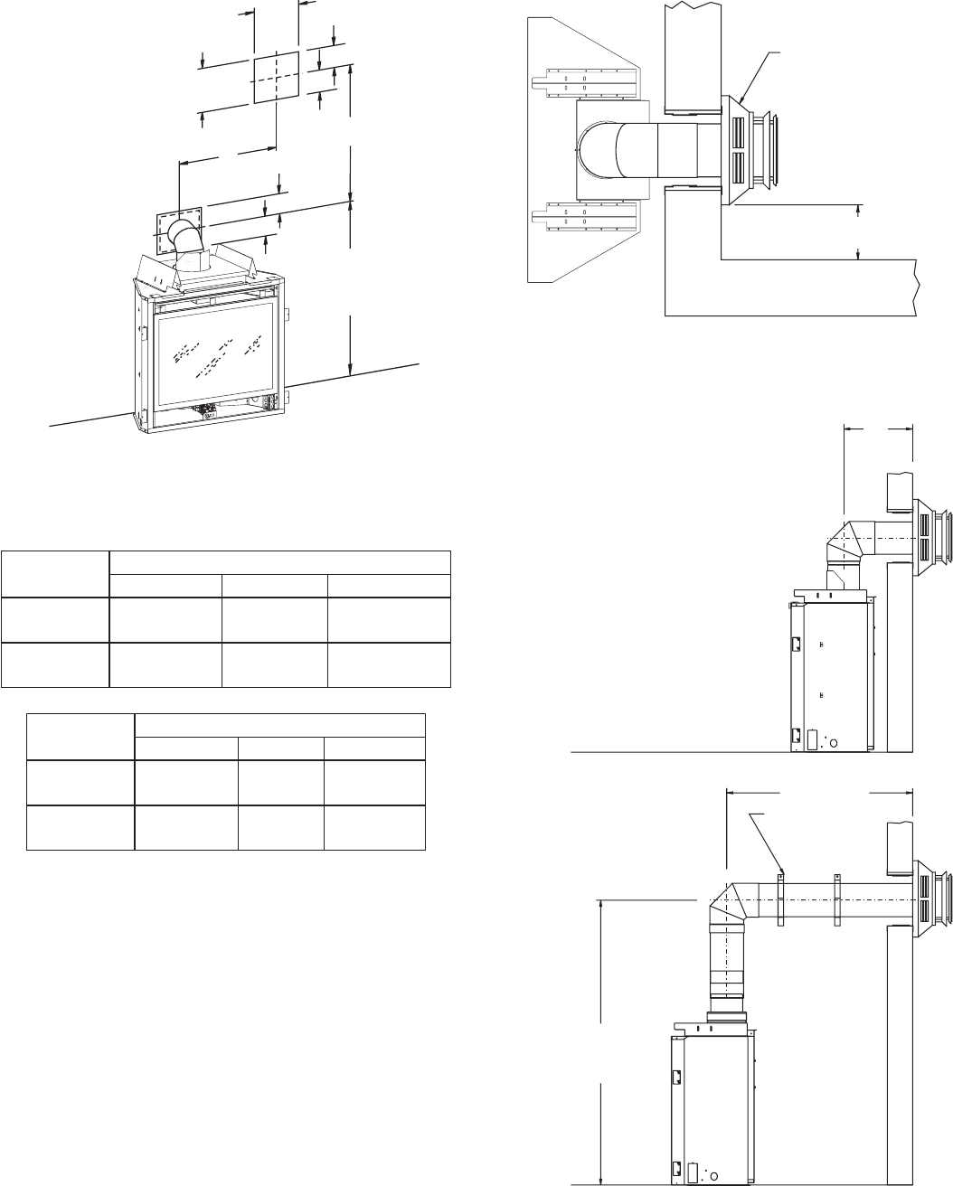
VENT CAP
9” (229mm) minimum
TO SIDE WALL
Figure 25
Figure 24
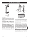
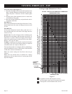
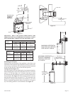
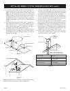
MINIMUM HOLE LOCATION DIMENSIONS FOR
THROUGH THE WALL HORIZONTAL INSTALLATIONS
WITH 90 DEGREE ELBOW OFF TOP OF FIREPLACE
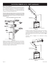
Positioning the Fireplace
Determine the exact position of the appliance so the direct vent
termination will be centered (if possible) between two (2) studs. This
will avoid any extra framing. All vent kit pipes should be assembled
on the unit after the unit is moved into the nal position.
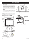
Cutting the Hole (Figure 23)
After the replace has been positioned in its permanent location,
the hole through the exterior wall of the house can be cut. This hole
must be 12" (305 mm) high x 10" (254 mm) wide with its center
line determined by the amount of vertical rise and horizontal run of
the termination. See Figure 23. When locating the hole it must be
noted that the bottom of the cap must be 12" (305 mm) above the
ground level, and top of the cap must be no less than 18" (457 mm)
below a combustible projection, and no closer than 9" (229 mm) to
any wall running parallel to vent termination. See Figure 24.
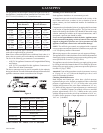
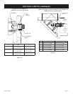
FIREPLACE
SERIES
HARD ELBOW DIMENSIONS
"A" "B" "C"
DVX36FP 43-1/2"
(1105 mm)
5"
(127 mm)
7"
(178 mm)
DVX42FP 43-1/2"
(1105 mm)
5"
(127 mm)
7"
(178 mm)
FIREPLACE
SERIES
FLEX PIPE 90 DEGREE BEND
"A" "B" "C"
DVX36FP 46"
(1143 mm)
5"
(127 mm)
7"
(178 mm)
DVX42FP 46"
(1143 mm)
5"
(127 mm)
7"
(178 mm)
Figure 23
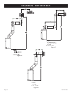
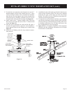
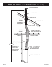
MAXIMUM HORIZONTAL
RUN WITH NO VERTICAL
RISE AND 90° ELBOW
3’
(914mm)
MAXIMUM HORIZONTAL
RUN WITH MINIMUM
VERTICAL RISE AND
90° ELBOW
20’ (6.1m)
PIPE STRAPS
EVERY2’ (61cm)
8’ (244cm)
TO BOTTOM
OF UNIT
SEE CHART FOR
PERMISSIBLE
“H”AND “V”
DIMENSIONS
A
CENTER OF ELBOW
STRAIGHT OUT
(MINIMUM)
10”
(254mm)
C
B
V
C
B
H
12”
(305mm)