


Page 9R-3451
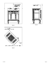
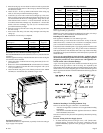
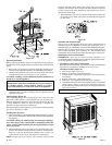
3. Place the casing top on a non-abrasive surface in order to protect the
porcelain finish. The exterior of the casing top should be facing the
non-abrasive surface.
4. Attach 11 5/8" x 11 5/8" top shield to the interior of the casing top
with (1) 3/8" bolt provided in hardware package.
5. Locate the (4) screw holes on the heat exchanger top. The screw
holes are 8 3/4" apart. Position the angled front edge on the 12" x 19
3/8" heat shield with the front of the appliance. Align the (4) tabs
with clearance holes on the 12" x 19 3/8" heat shield with the (4)
screw holes on the heat exchanger top. Attach the 12" x 19 3/8" heat
shield to the heat exchanger top with (4) 1/2" hex-head screws
provided in hardware package.
6. Place the casing top onto the outer casing. The casing top nests into
the outer casing.
7. Insert center stone inlay, left stone inlay and right stone inlay into
casing top.
8. Installation of stone inlay is completed.
Parts List
Part Part Quantity
Description Number Supplied
11 5/8" x 11 5/8" Top Shield CI-091 1
12" x 19 3/8" Heat Shield CI-092 1
3/8" Bolt R-3646 1
1/2" Hex-Head Screw R-2737 4
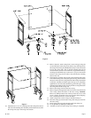
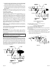
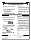
Installation of Wire Channel Assembly (Figure 10)
The ON/OFF/REMOTE switch with harness is factory installed into the
switch box.
After the appliance housing is installed into the cast iron outer casing the
wire channel can be installed.
1. Attach switch box on the left side of casing back with (2) 10 x 1/2"
provided screws.
2. Route wires from ON/OFF/REMOTE switch within wire channel.
3. Attach wire channel on the left side of the casing back with (4) 10
x 1/2" provided screws.
4. Attach the black and green (wires) female push-ons to the TH/TP
and TH (two outside male tabs) terminals on gas valve.
Figure 10
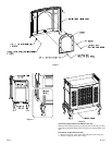
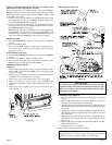
Gas Supply (Figure 11)
Check all local codes for requirements, especially for the size and type
of gas supply line required.
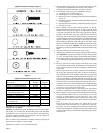
Recommended Gas Pipe Diameter
Pipe Length Schedule 40 Pipe Tubing, Type L
(Feet) Inside Diameter Outside Diameter
Nat. L.P. Nat. L.P.
0-10 1/2" 3/8" 1/2" 3/8"
1.3 cm 1.0 cm 1.3 cm 1.0 cm
10-40 1/2" 1/2" 5/8" 1/2"
1.3 cm 1.3 cm 1.6 cm 1.3 cm
40-100 1/2" 1/2" 3/4" 1/2"
1.3 cm 1.3 cm 1.9 cm 1.3 cm
100-150 3/4" 1/2" 7/8" 3/4"
1.9 cm 1.3 cm 2.2 cm 1.9 cm
Note: Never use plastic pipe. Check to confirm whether your local codes
allow copper tubing or galvanized.
Note: Since some municipalities have additional local codes, it is always
best to consult your local authority and installation code.
Installing a New Main Gas Cock
Each appliance should have its own manual gas cock.
A manual main gas cock should be located in the vicinity of the unit.
Where none exists, or where its size or location is not adequate, contact
your local authorized installer for installation or relocation.
Compounds used on threaded joints of gas piping shall be resistant to the
action of liquefied petroleum gases. The gas lines must be checked for
leaks by the installer. This should be done with a soap solution watching
for bubbles on all exposed connections, and if unexposed, a pressure test
should be made.
Never use an exposed flame to check for leaks. Appliance must be
disconnected from piping at inlet of control valve and pipe capped or
plugged for pressure test. Never pressure test with appliance con-
nected; control valve will sustain damage!
A gas valve and ground joint union should be installed in the gas line
upstream of the gas control to aid in servicing. It is required by the
National Fuel Gas Code that a drip line be installed near the gas inlet. This
should consist of a vertical length of pipe tee connected into the gas line
that is capped on the bottom in which condensation and foreign particles
may collect.
Figure 11
Method of Installing a Tee Fitting Sediment Trap
The use of the following gas connectors is recommended:
— ANS Z21.24 Appliance Connectors of Corrugated Metal Tubing
and Fittings
— ANS Z21.45 Assembled Flexible Appliance Connectors of Other
Than All-Metal Construction
The above connectors may be used if acceptable by the authority having
jurisdiction.
Pressure Testing of the Gas Supply System
1. To check the inlet pressure to the gas valve, a 1/8" (3mm) N.P.T.
plugged tapping, accessible for test gauge connection, must be
placed immediately upstream of the gas supply connection to the
appliance.