


Page 7R-3451
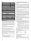
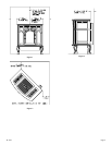
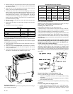
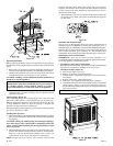
Figure 6
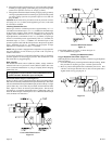
10. Attach the (4) 1-1/4" x 1/2" retaining tabs to the casing front with (4)
3/8" bolts. The retaining tabs should be positioned downward, from
the casing front, top to the casing front, bottom.
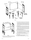
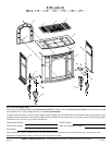
11. Refer to Figure 8, attach casing front to outer casing by using the
(4) retaining tabs on the casing front. The (2) top, retaining tabs on
the casing front will be placed behind the (2) top, locator tabs on the
front of the casing sides. The (2) bottom, retaining tabs will be
inserted into the (2) 9/16" slots on the front, leg pads. Place the top,
retaining tabs behind the top, locator tabs as you pivot inward the
bottom of the casing front in order to insert the bottom, retaining
tabs into the slots.
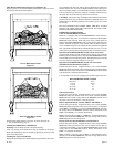
12. The following procedure will provide a snug fit between the casing
front and the casing sides. Grasp the right, front leg, push inward on
the leg in order to provide a snug fit between the casing front and the
casing side. Continue to hold the right, front leg as you completely
tighten the (2) 3/8" bolts that attach the leg pad to the right, casing
side. Repeat procedure for left, front leg to achieve a snug fit between
the casing front and the casing side.
13. Remove the casing front from the outer casing.
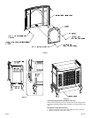
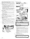
14. Refer to Figure 9, the appliance firebox can now be inserted into the
outer casing. Center the firebox in the outer casing. Attention:
Remove (1) Phillips-head screw in the top of the valve cover. The
screw is used to secure the valve cover in place during shipping.
The (1) Phillips-head screw can be discarded.
15. Attach casing front to outer casing as described in Step 11.
16. Place the casing top onto the outer casing. The casing top nests into
the outer casing.
17. Insert center grille, left grille and right grille into casing top.
18. Level appliance by adjusting leveling bolts.
19. Assembly of cast iron (outer casing) stove casting is completed.
Figure 5