


Page 19R-3451
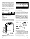
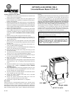
OPTIONAL BLOWER CIB-2
Unvented Room Heater CIVF-25
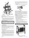
Installing Optional CIB-2 Blower
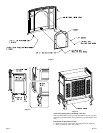
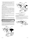
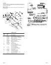
1. Loosen, but do not remove, (4) hex-head screws located on the
exterior, bottom of the appliance.
2. Position the blower assembly at the rear of the appliance. The
blower assembly has (4) keyholes for attachment to the exterior,
bottom of the appliance.
3. Place the large diameter holes in the keyholes over and behind the
(4) hex-head screws that were loosened in Step 1. Push inward on
the blower assembly to lock the keyholes into position behind the
screws. Tighten (4) hex-head screws to secure blower assembly to
exterior, bottom of the appliance.
4. Remove wire channel from rear cover by removing (4) hex-head
screws. Note: If optional blower is being installed during initial
installation of appliance, the wire channel will not be attached to
casing back. (Refer to Installation of
Wire Channel Assembly,
Page 9)
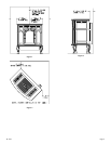
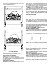
5. Remove casing top and casing front from outer casing.
6. If optional stone inlay is installed in casing top, remove the 12" x
19 3/8" heat shield from the heat exchanger top by removing (4)
1/2" hex-head screws.
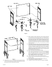
7. When facing the rear of the appliance, insert fan control shield
between rear cover and inner body of appliance on the left side of
the rear cover.
8. Attach fan control shield to top of inner body with (2) #10 x 1/2"
screw provided in hardware package.
9. If applicable, attach 12" x 19 3/8" heat shield to heat exchanger top
with (4) 1/2" hex-head screws from Step 6.
10. Place the casing top onto the outer casing. The casing top nests
into the outer casing.
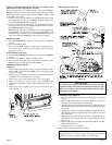
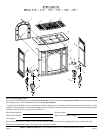
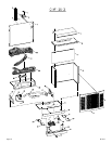
11. Attach fan control to FLAT, fan control bracket (Part 9A, Page 20)
with (2) 6 x 1/4" screws provided in hardware package.
12. Attach fan control with bracket onto the wire channel by using (2)
8 x 1/4" screws provided in hardware package.
13. Route wires from fan control and ON/OFF/REMOTE switch
within wire channel.
14. When facing the rear of the appliance, align and insert fan control
with bracket into 1 3/8" x 2" opening on the left side of the rear
cover.
15. Attach wire channel to rear cover by using (4) hex-head screws
removed in Step 4. (Refer to Installation of
Wire Channel
Assembly, Page 9)
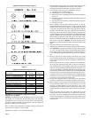
16. Insert AUTO/OFF/ON switch into rectangular notch on valve
bracket. Be sure to insert AUTO/OFF/ON switch with letters
(words) upright. (See wiring diagram)
17. Attach 1/4" push-on terminal from blue wire on the fan control
to the AUTO (top) tab on the switch.
18. Attach 1/4" push-on terminal from black wire to the OFF
(middle) tab on the switch.
19. Attach 1/4" push-on terminal from white wire on the fan
control to the ON (bottom) tab on the switch.
20. Installation of optional CIB-2 blower is completed.
Fan Control
The fan control is a non-adjustable automatic type. The fan control
will require between 5 and 10 minutes of main burner operation
before the fan control "closes" and activates the blower. The blower
will continue to run between 5 and 10 minutes after the main burner
shuts off, before the fan control "opens" and deactivates the blower.
Wiring
The appliance, when installed, must be electrically grounded in accordance
with local codes or, in the absence of local codes, with the National
Electrical Code ANSI/NFPA No. 70, if an external electrical source is
utilized. This appliance is equipped with a three-prong [grounding]
plug for your protection against shock hazard and should be
plugged directly into a properly grounded three-prong receptacle.
Do not cut or remove the grounding prong from this plug. For an
ungrounded receptacle, an adapter, which has two prongs and a wire
for grounding, can be purchased, plugged into the ungrounded
receptacle and its wire connected to the receptacle mounting screws.
With this wire completing the ground, the appliance cord plug can
be plugged into the adapter and be electrically grounded.
CAUTION: Label all wires prior to disconnection when servicing
controls. Wiring errors can cause improper and dangerous operation.
Verify proper operation after servicing.
WARNING:
Unplugging of blower accessory will not stop the heater from
cycling. To shut heater off: Turn temperature dial or
thermostat to lowest setting. Turn knob on gas control to
"OFF", depressing slightly. Do not force.