


7
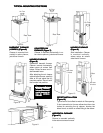
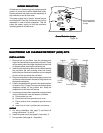
7. With the cabinet installed, the air cleaner can now be
wired to electrical input source.
WARNING
!
Installation of this unit must comply with localInstallation of this unit must comply with local
Installation of this unit must comply with localInstallation of this unit must comply with local
Installation of this unit must comply with local
electric codes or other applicable codes.electric codes or other applicable codes.
electric codes or other applicable codes.electric codes or other applicable codes.
electric codes or other applicable codes.
Review and understand local codes prior to instal-Review and understand local codes prior to instal-
Review and understand local codes prior to instal-Review and understand local codes prior to instal-
Review and understand local codes prior to instal-
lation.lation.
lation.lation.
lation.
Failure to do so could result in serious personalFailure to do so could result in serious personal
Failure to do so could result in serious personalFailure to do so could result in serious personal
Failure to do so could result in serious personal
injury or death.injury or death.
injury or death.injury or death.
injury or death.
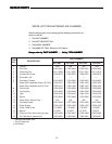
8. An air cleaner unit with no air flow monitor requires
electrical wiring through the furnace controls. Con-
nect wiring to the furnace control terminals (EAC-H)
for power, (EAC-N) for neutral and connect metal
frame of EAC to ground.
If the air cleaner unit has an air flow monitor, it must be
connected to 120 VAC 60 Hz. A 20 amp circuit is more
than adequate. If an air flow monitor is not installed but
is required for operation, order Air Flow Kit F859-
0381. If a power cord is required, order F97-0019.
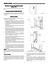
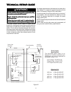
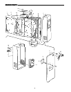
9. Remove junction box cover and install the required
bushing into the 3/4 in. Knock out. With the supply
voltage turned off, route three (3) wires into junction
box for connections. (See Fig. 17.)
Insure all wires are clamped, wire connectors prop-
erly installed and grommets used to prevent wire
abrasion.
Vertical
Section
Wood Block
Tape All
Joints
Figure 16
Hot
Neutral
Grounding
Conductor
Front View
Figure 17
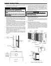
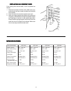
Cabinet
Pre-Filters
Handle
Contact
Button
Contact
Button
Collecting Cells
Power Pack
Figure 18
WIRING INSTRWIRING INSTR
WIRING INSTRWIRING INSTR
WIRING INSTR
UCTIONSUCTIONS
UCTIONSUCTIONS
UCTIONS
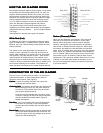
11. With the cabinet Installed, reinstall pre-filter(s) and
collecting cell(s) (Figure 18).
NOTE: The contact button and handles on the cell
must be facing you and ionizing wires must be on the
air intake side.
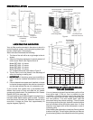
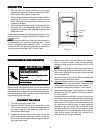
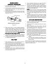
12. Install the power pack as follows:
Engage the lip on lower inside edge of power pack in
the flange on cabinet and carefully close the power
pack, making sure that the electrical connector prongs
on the power pack enter the slots in the socket on
cabinet. When the power pack is fully in place, engage
the latch and snap it closed.
Side Edge of
Power Pack
Power Pack
Male Plug
Female Plug
Cabinet
Press to Close After
Latch is Engaged
Latch
To Engage
Engage Lip on Lower Inside Edge
of Power Pack in Flange.
Figure 19 Installing Power Pack
10. If this unit has an electrical cord, the cord has a
grounding type plug with a third (grounding) pin. This
plug will fit only into a grounding type power outlet. If
the proper type of outlet is not available, contact
qualified personnel to install a proper outlet. Do not
alter the plug in any way.
▲
!
WW
WW
W
ARNINGARNING
ARNINGARNING
ARNING
To reuce the risk of electric shock, The power cordTo reuce the risk of electric shock, The power cord
To reuce the risk of electric shock, The power cordTo reuce the risk of electric shock, The power cord
To reuce the risk of electric shock, The power cord
must be connected to an appropriate outlet. Do notmust be connected to an appropriate outlet. Do not
must be connected to an appropriate outlet. Do notmust be connected to an appropriate outlet. Do not
must be connected to an appropriate outlet. Do not
alter the plug in any way.alter the plug in any way.
alter the plug in any way.alter the plug in any way.
alter the plug in any way.