


12
POWER SUPPLYPOWER SUPPLY
POWER SUPPLYPOWER SUPPLY
POWER SUPPLY
CHECKOUT PROCEDURECHECKOUT PROCEDURE
CHECKOUT PROCEDURECHECKOUT PROCEDURE
CHECKOUT PROCEDURE
1. Turn power switch to the “OFF” position and remove
the power pack from cabinet.
2. If air flow switch is installed, locate air flow switch and
remove power pack cover. If air flow switch is not
installed, go to step 4.
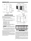
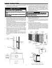
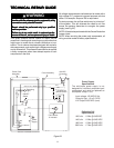
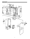
3. Disconnect the three-pin plastic connector and jumper
the two female pins (white wire to white-brown wire)
as shown in Fig. 23.
Jumper Lead
Female Pins
Male Pin
Plastic Connector
Method of jumping lead wires of
connector plug from air flow switch.
Figure 23
4. Place power pack on a well insulated workbench.
Connect meter negative (-) lead to the sheet metal
chassis and the high voltage probe to high voltage
contact on back cover of power pack. Connect AC
power to power pack using an extension cord and turn
power switch to the “ON” position.
Keep hands andKeep hands and
Keep hands andKeep hands and
Keep hands and
tools away from high voltage contact.tools away from high voltage contact.
tools away from high voltage contact.tools away from high voltage contact.
tools away from high voltage contact.
5. If Operating Light comes ON and output voltage is
between 6100 and 6800 VDC, power supply is good.
6. If voltage is good but Operating Light does not come
on, replace Operating Light.
CELL TESTCELL TEST
CELL TESTCELL TEST
CELL TEST
1. Place collecting cell on a well insulated workbench
with the cell contact button pointing upward.
2. Select a power pack (with air flow switch bypassed
and ozone reduction jumper intact) that reads be-
tween 6100 and 6800 VDC at the cell contact with no
cell attached.
3. Place power pack on top of collecting cell ensuring
that there is proper contact between the cell contact
on the power pack contact.
4. Using a standard extension cord, apply 120 VAC to
power pack. Turn power switch to “ON” position.
5. Connect meter negative (-) lead to metal frame of
collecting cell. Use high voltage probe to measure
voltage at collecting cell ionizer or cell plates. Voltage
should be 6100 to 6800 VDC.
NOTE:NOTE:
NOTE:NOTE:
NOTE: A new “out-of-box” cell may cause the voltage
to be lower than normal for a short period of time. To
obtain a more accurate measurement, “age” the cell
by applying high voltage to the cell for 15 to 30
minutes.
6 If voltage is below 6100 VDC, check cell for foreign
objects, bowed/bent/loose plates, broken ionizing
wires or cracked insulators. Wash cells if required. If
Operating Light remains OFF, replace collecting cell.
AIR FLOW MONITOR TESTAIR FLOW MONITOR TEST
AIR FLOW MONITOR TESTAIR FLOW MONITOR TEST
AIR FLOW MONITOR TEST
1. Connect a multimeter set to read 120 VAC to power
supply terminals marked “LINE.”
2. Connect 120 VAC to power pack plug, turn power
switch “ON.”
3. Blow on thermistor at air flow monitor. 120 VAC
should appear at multimeter. Stop blowing and volt-
age should disappear in 10 - 15 seconds.
4. If voltage did not appear (Step 3), disconnect power to
power pack. Locate air flow switch and remove power
pack cover. Disconnect the three-pin plastic connec-
tor. Jumper the two female pins (white wire to white-
brown wire) as shown in Fig. 23. Reconnect power to
power pack. Turn power switch “ON.”
A. If 120 VAC appears at multimeter, replace air flow
monitor.
B. If 120 VAC does not appear on multimeter, prob-
lem is other than air flow monitor. Recheck all
primary wiring.
NOTE: The air flow monitor is designed to operate in the
temperature range of 65° to 120° F. Operation outside this
range is not recommended.