


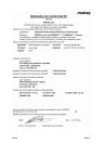
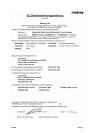
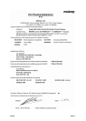
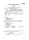

IP258/SI
Page 2
GB
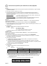
Instructions specific to hazardous area installations
General
1. Installation of this equipment shall be carried out by suitably trained personnel, in accordance with the
applicable code of practice.
2. The user should not repair this equipment.
3. If the equipment is likely to come into contact with aggressive substances, it is the responsibility of the user to
take suitable precautions that prevent it from being adversely affected, thus ensuring that the type of
protection is not compromised.
Aggressive Substances
: – e.g. acidic liquids or gases that may attack metals or solvents that may affect
polymeric materials.
Suitable Precautions
: – e.g. regular checks as part of routine inspections or establishing from the
material’s data sheet that it is resistant to specific chemicals.
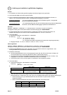
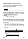
Sensors
Model numbers covered: MSM433A***, MSM448A*** (“*” indicates options in construction, function and materials.)
The following instructions apply to equipment covered by certificate number ITS00ATEX2003:
1. The equipment may be used with flammable gases and vapours with apparatus groups IIA, IIB & IIC and with
temperature classes T1, T2, T3, T4, T5 & T6.
2. Technical data:
a. Materials of construction: Refer to Part numbering identification chart.
b. Coding: II 1 G
EEx ia IIC T6 (-40°C Ta +80°C)
T4 (-40°C Ta +120°C)
Ta = the higher of the process or ambient temperature.
c. Input parameters: Ui= 4.6V, Ii= 162mA, Pi= 0.2W, Ci= 14nF, Li= 0.1mH
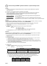
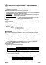
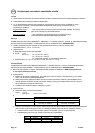
Control Unit
Model numbers covered: MSM400, MSM400/S* (“*” indicates options in construction, function and materials.)
The following instructions apply to equipment covered by certificate number ITS00ATEX2002:
1. The MSM400 control unit may be connected to a transmitter located in a hazardous area. The MSM control
unit must not itself be located in a hazardous area.
2. Wiring instructions
a. The MSM must not be connected to a supply exceeding 250V r.m.s. or dc, or to apparatus containing a
source of voltage exceeding 250V r.m.s. or dc.
b. The Intrinsically Safe outputs of the MSM Control Unit may be connected to certified equipment used in a
hazardous area requiring category 1 equipment, with flammable gases and vapours with apparatus groups
IIC, IIB and IIA. No additional I.S. barrier is required.
c. The fuse must only be replaced with the type specified.
3. Technical data:
a. Materials of construction: Refer to Part numbering identification chart.
Coding: II (1) G
[EEx ia] IIC (-40°C Ta +55°C)
b.
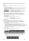
Channel 1 (Rx) Channel 2 (Tx)
Terminal numbers 1, 2 3
Cable Screen Terminal 5, 6 4
Parameters:
Uo= 1.2V, Io= 42.1mA, Po=
13mW, Ci= 0.4nF, Li= 0.04mH
Uo= 4.6V, Io= 162mA, Po = 0.2W,
Ci= 0.4nF, Li= 0.04mH
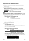
c. Cables: The cable between the Control Unit and Sensors must be a separate cable or multicore cable
which must be of Type A or Type B as defined in EN50039:1980 subject to the following:
• The curcuit from each channel must be individually screened when used within Type A multicore cable.
• The peak voltage with a type B multicore must not exceed 60V
Group Capacitance Inductance or L/R Ratio
IIC 99.9 ȝF 0.7 mH 98 ȝH/ȍ
IIB 490 ȝF 4.8 mH 973 ȝH/ȍ
IIA 490 ȝF 8.8 mH 1253 ȝH/ȍ