


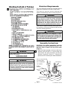
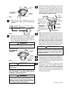
9. Screw the eye screw (supplied) into the joist
7 inches from the center of the ceiling outlet box
(Figure 6).
10. Carefully lift the fan and seat the hanger
ball/downrod assembly on the hanger bracket
that was just attached to the outlet box (Figure 7).
Be sure the groove in the ball is lined up with the
tab on the hanger bracket (Figure 5).
If you feel that you do not have enough electrical
wiring knowledge or experience, have your fan
installed by a licensed electrician.
5
TWO SCREWS
SUPPLIED WITH
OUTLET BOX
HANGER
BRACKET
TAB
OUTLET
BOX
Figure 5
7"
EYE SCREW
OUTLET BOX
Figure 6
OUTLET
BOX
HANGER
BRACKET
HANGER BALL/
DOWNROD
ASSEMBLY
NOTE: CEILING COVER,
SUPPLY WIRES AND
FAN WIRES OMITTED
FOR CLARITY.
Figure 8
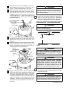
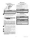
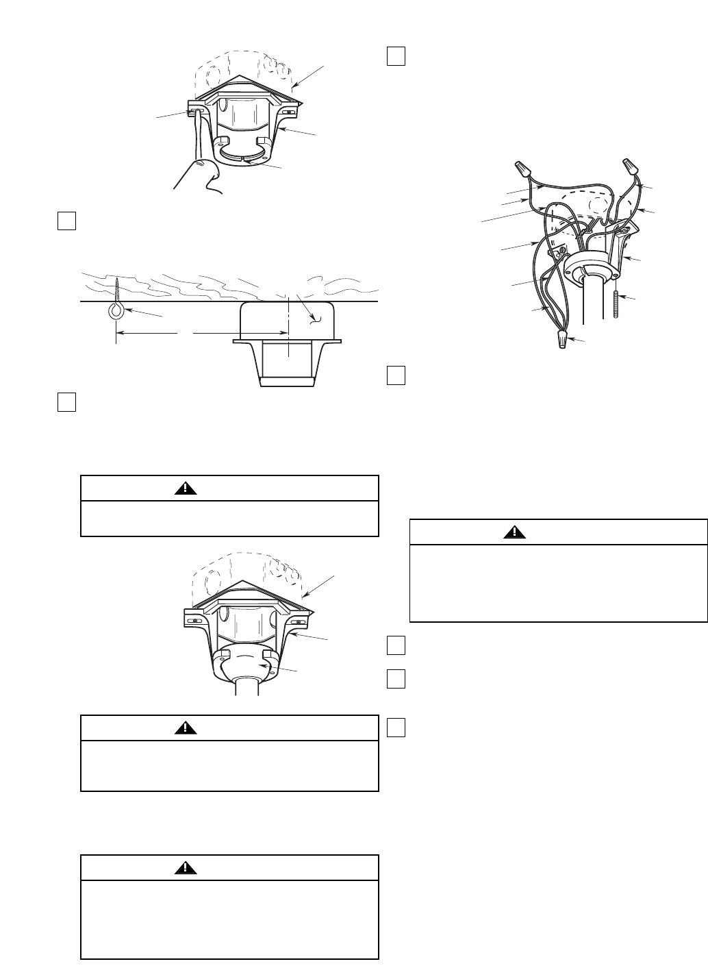
11. Connect the green grounding wire from the
hanger ball, the green grounding wire from
the hanger bracket, and the green grounding wire
from the fan to the grounding conductor of the
supply (this may be a bare wire or wire with green
colored insulation). Securely connect wires with
wire connectors (supplied) (Figure 8).
12. Securely connect the fan motor white wire to the
supply white (neutral) wire using wire connector
supplied (Figure 8). Securely connect the fan
motor black wire to the supply black (hot) wire
using wire connector supplied (Figure 8). After
connections have been made, turn leads upward
and carefully push the leads into the outlet box,
with the wires spread apart and the white and
green leads on one side of the outlet box and the
black leads on the other side of the outlet box.
13. Screw the two 3/4” threaded studs (supplied) into
the tapped holes in the hanger bracket (Figure 8).
14. Lift the ceiling cover up to the threaded studs and
turn until studs protrude through the holes in the
ceiling cover (Figure 9).
15. Secure the ceiling cover in place by sliding
lockwashers over the threaded studs and
installing the two knurled knobs (supplied)
(Figure 9). Tighten the knurled knobs securely
until the ceiling cover fits snugly against the
ceiling. Your fan is now wired to be turned on and
off from the wall switch.
To avoid possible electrical shock, be sure electricity
is turned off at the main fuse box before wiring.
NOTE: If you are not sure if the outlet box is
grounded, contact a licensed electrician for advice,
as it must be grounded for safe operation.
WARNING
THREADED
STUD (2)
HANGER
BRACKET
WHITE
SUPPLY
(NEUTRAL)
GREEN WIRE (GROUND)
FROM HANGER BRACKET
LISTED WIRE
CONNECTOR (3)
SUPPLY GROUND
WIRE
GREEN WIRE
(GROUND) FROM
HANGER BALL
BLACK FAN WIRE
BLACK
SUPPLY
(HOT)
WHITE
FAN WIRE
GREEN WIRE
(GROUND) FROM FAN
Figure 8
Failure to seat tab in groove could cause damage to
electrical wires and possible shock or fire hazard.
WARNING
To avoid possible fire or shock, do not pinch wires
between the hanger ball/downrod assembly and
hanger bracket.
WARNING
Check to see that all connections are tight, including
ground, and that no bare wire is visible at the wire
connectors, except for the ground wire. Do not
operate fan until blades are in place. Noise and fan
damage could result.
WARNING
U.L. Model No.: HF1160