


7. Install two setscrews (previously removed in
Step 2) in the motor yoke (Figure 3). While pulling
up on the hanger ball, securely tighten both
setscrews using the setscrew wrench (supplied).
NOTE: The setscrews must be properly installed
as described above, or fan wobble could result.
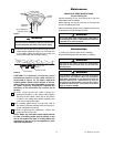
8. Securely attach the hanger bracket to the outlet
box using the two screws supplied with the
outlet box (Figure 5).
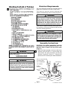
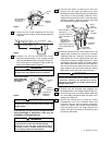
2. Using the setscrew wrench (supplied), remove the
two setscrews from the top of the motor yoke
(Figure 1). Retain the setscrews for future use.
3. Route the three 48” motor leads and the safety
cable through the center hole in the motor cover.
Align the two holes in the motor cover with the
threaded holes in the motor yoke and secure by
installing two M4-.7 x 10mm pan head knurled
screws and two M4 external tooth lockwashers
(supplied) (Figure 2).
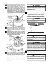
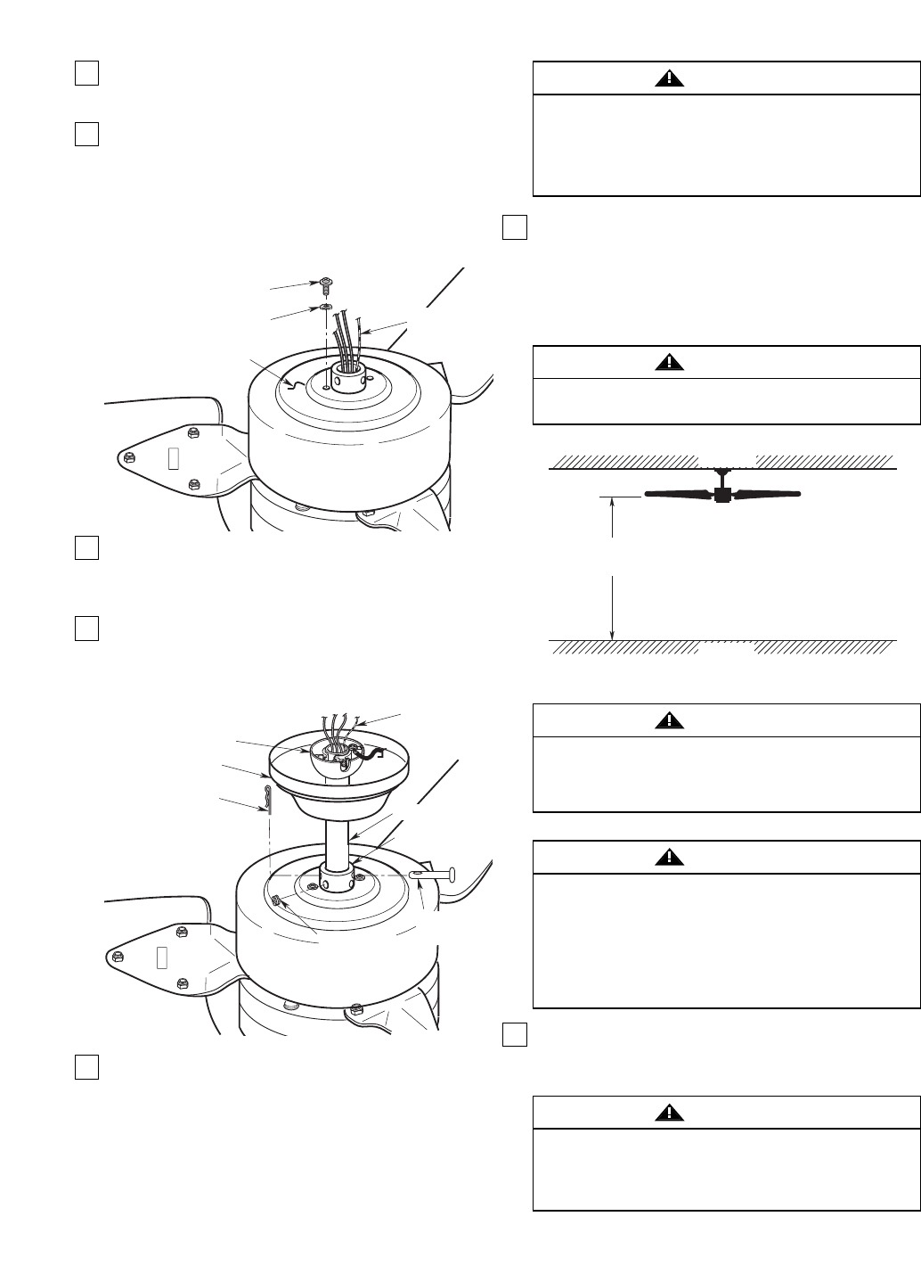
4. Route the three motor leads and the safety cable
through the center hole in the ceiling cover and
position the ceiling cover over the motor yoke
(Figure 3).
5. Separate, untwist and unkink the three motor leads
and the safety cable, then route them through the
hanger ball/downrod assembly and seat the
downrod in the motor yoke (Figure 3).
6. Align the clevis pin holes in the downrod with the
holes in the motor yoke. Install the clevis pin and
secure with the hairpin clip (Figure 3). The clevis
pin must go through the holes in the motor yoke It
is critical that the clevis pin in the motor yoke is
properly installed and the setscrews securely
tightened. Failure to verify that the pin and
setscrews are properly installed could result in the
fan falling.
4
It is critical that the clevis pin in the motor coupling
is properly installed and the setscrews securely
tightened. Failure to verify that the pin and setscrews
are properly installed (as shown in Figure 3) could
result in the fan falling.
WARNING
SAFETY
CABLE
CEILING COVER
HANGER
BALL/DOWNROD
ASSEMBLY
HAIRPIN
CLIP
SETSCREW
MOTOR YOKE
DOWNROD
CLEVIS
PIN
FLOOR
CEILING
AT LEAST
10'
Figure 4
Figure 3
The fan must be hung with at least 10' of clearance
from floor to blades (Figure 4).
WARNING
The outlet box and joist must be securely mounted
and capable of supporting at least 50 lbs. Use only a
U.L. outlet box listed as “Acceptable for Fan Support
of 50 lbs. or less”.
WARNING
To reduce the risk of fire, electric shock, or personal
injury, mount fan to outlet box marked “Acceptable
for Fan Support of 50 lbs. or less”, and use screws
supplied with outlet box. Most outlet boxes
commonly used for support of light fixtures are not
acceptable for fan support and may need to be
replaced. Consult a qualified electrician if in doubt.
WARNING
Hanger bracket must seat firmly against outlet box. If
the outlet box is recessed, remove wall board until
bracket contacts box. If bracket and/or outlet box are
not securely attached, the fan could wobble or fall.
WARNING
MOTOR COVER
M4 EXTERNAL TOOTH
LOCKWASHER
M4-.7 x 10mm PAN HEAD
KNURLED SCREW
SAFETY
CABLE
Figure 2
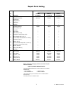
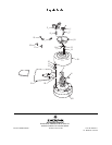
U.L. Model No.: HF1160