


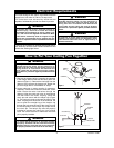
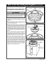
LIGHT KIT ASSEMBLY WHITE
WIRE CONNECTOR
CEILING FAN WHITE WIRE
CONNECTOR
LIGHT KIT ASSEMBLY BLACK
WIRE CONNECTOR
CEILING FAN BLACK WIRE
CONNECTOR
LIGHT KIT ASSEMBLY
7
Model No.: CF990
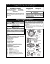
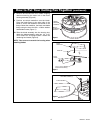
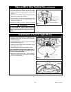
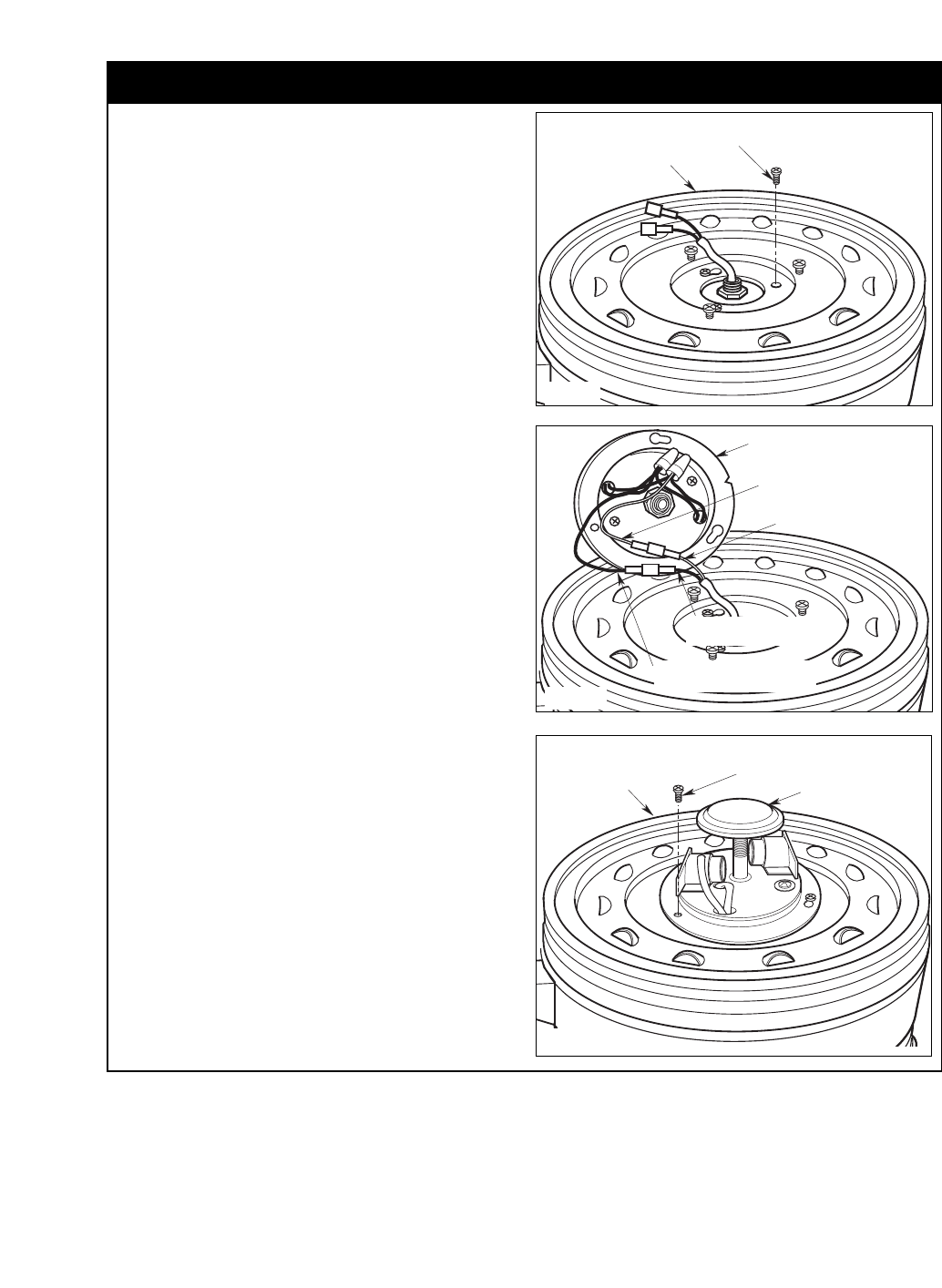
11. Remove one #8-32 x 10mm serrated head screw
from the fan motor housing (reserve for later
use). Loosen the other two screws to assemble
the lower housing to the fan motor housing
(Figure 9).
12. Position the lower housing onto the fan motor
assembly, aligning each of the the three holes.
Attach the lower housing to the fan motor
assembly using the three #8-32 x 10mm serrated
head screws. Rotate the lower housing to
securely tighten by engaging the screws in the
two key hole slots (Figure 9).
NOTE: Make sure wires are not pinched between
fan motor assembly and lower housing.
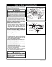
13. Attach the white wire connector from the ceiling
fan to the white wire connector of the light kit
assembly (Figure 10). Connect the black wire
connector from the ceiling fan to the black wire
connector of the light kit assembly.
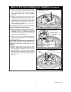
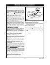
14. Remove one of the one of the three screws in the
lower housing and loosen the remaining two
screws (Figure 11).
NOTE: Make sure all wires and connector are
tucked under the light kit assembly and not
pinched between light kit assembly and lower
housing.
15.Position the light kit assembly onto the lower
housing, aligning each of the the three holes.
Attach the light kit assembly to the lower housing,
using three #8-32 x 10mm serrated head screws.
Rotate the light kit assembly to securely tighten
by engaging the screws in the two key hole slots
(Figure 11).
How to Put Your Ceiling Fan Together (continued)
#8-32 x 10mm SERRATED
HEAD SCREW (3)
LOWER
HOUSING
LIGHT KIT ASSEMBLY
Figure 11
#8-32 x 10mm
SERRATED HEAD SCREWS (3)
LOWER HOUSING
Figure 9
Figure 10