


9
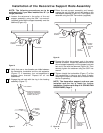
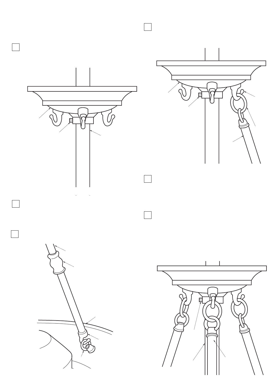
Installation of the Decorative Support Rods Assembly
NOTE: The following procedures are to be
performed only if you have installed the 18” (or
longer) downrod.
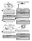
1. Loosen the setscrew in the collar of the rod
support assembly using the 5/64” hex wrench
(supplied) and slide the support assembly over the
downrod (Figure 16).
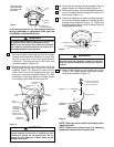
2. Verify that one or two threads are visible between
the decorative turnbuckle and the rod segments
(Figure 17). If necessary, turn rod segments to
expose more threads. Repeat for all rod
assemblies.
3. Engage the rod hook with the ring in the housing
assembly (Figure 17).
SETSCREW
ROD SUPPORT
ASSEMBLY
DOWNROD
Figure 16
RING
HOOK
HOUSING
ASSEMBLY
ROD SEGMENT
DECORATIVE TURNBUCKLE
(ROTATE THE TURNBUCKLE
TO REMOVE SLACK IN ROD
ASSEMBLY; SEE STEP 6)
Figure 17
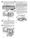
4. Raise the rod support assembly and loosely
engage the rod ring with one of the hooks on the
rod support assembly (Figure 18). Then tighten the
setscrew using the 5/64” hex wrench (supplied).
5. Engage the other two support rods in the same
manner as above. Loosen the setscrew and raise
the rod support assembly until the support rods are
taut and in line with the downrod (Figure 19). Then
securely tighten the setscrew using the 5/64” hex
wrench.
6. Tighten (rotate) the turnbuckles (Figure 17) of the
rod assemblies to take up any slack, thereby
reducing the chance of noise due to vibration when
the fan is operating.
NOTE: The decorative support rods are now
installed and the fan is ready for further
installation. Continue with Step 4 in CEILING FAN
PROCEDURES, Page 5.
ROD
ASSEMBLY
SETSCREW
ROD SUPPORT
ASSEMBLY
LOOSELY
ENGAGE
ROD RING
WITH
HOOK
HOOK
Figure 18
SETSCREW
SUPPORT RODS
SHOULD BE
IN LINE WITH
DOWNROD
DOWNROD
Figure 19