


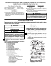
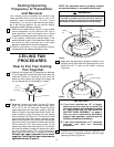
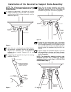
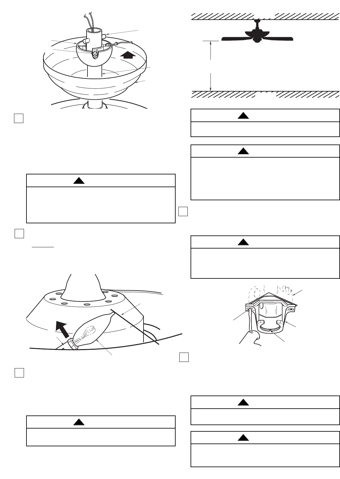
5. Reinstall the hanger ball (Figure 5) on the downrod as
follows. Route the two 80” motor leads through the
hanger ball. Position the pin through the two holes in
the downrod and align the hanger ball so the pin is
captured in the groove in the top of the hanger ball.
Pull the hanger ball up tight against the pin. Securely
tighten the setscrew in the hanger ball.
A loose setscrew could create fan wobble.
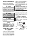
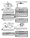
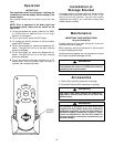
6.Screw in four 40-watt (maximum) candelabra base
lamps in the housing sockets (Figure 6). Grasp the
sockets and pivot them until the lamp bulbs are
even with the outer edge of the housing as shown.
This will provide the optimum lighting effect.
7.The fan comes with black and white leads that are
80” long. Before installing fan, measure up approxi-
mately 6 to 9-inches above top of hanger ball/down-
rod assembly. Cut off excess leads and strip back
insulation 1/2-inch from end of leads.
6
CEILING COVER
DOWNROD
PIN
HANGER
BALL
SETSCREW
Figure 5
It is critical that the pin in the hanger ball is properly
installed and the setscrew securely tightened.
Failure to verify that the pin and setscrew are proper-
ly installed could result in the fan falling.
WARNING
!
TOP ALIGN WITH
OUTER EDGE OF
THE HOUSING
CANDELABRA
BASE LAMP
SOCKET
Figure 6
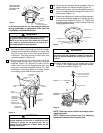
AT LEAST
7'
CEILING
FLOOR
Figure 7
To reduce the risk of fire, electric shock, or personal
injury, mount fan to outlet box marked acceptable for
fan support, and use screws supplied with outlet
box. Most outlet boxes commonly used for support
of light fixtures are not acceptable for fan support
and may need to be replaced. Consult a qualified
electrician in in doubt.
The outlet box must be securely anchored and capable
of withstanding a load of at least 50 lbs.
WARNING
!
WARNING
!
The fan must be hung with at least 7' of clearance
from floor to blades (Figure 7).
WARNING
!
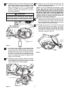
Hanger bracket must seat firmly against outlet box. If
the outlet box is recessed, remove wall board until
bracket contacts box. If bracket and/or outlet box are
not securely attached, the fan could wobble or fall.
TWO SCREWS
SUPPLIED WITH
OUTLET BOX
HANGER
BRACKET
TAB
OUTLET
BOX
Figure 2
Figure 8
9. Carefully lift the fan and seat the hanger ball/down-
rod assembly on the hanger bracket that was just
attached to the outlet box (Figure 9). Be sure the
groove in the ball is lined up with tab on the hanger
bracket (Figure 8).
WARNING
!
8.Securely attach the hanger bracket to the outlet box
using the two screws supplied with the outlet box.
(Figure 8.)
To avoid possible fire or shock, do not pinch wires
between the hanger ball/downrod assembly and
hanger bracket.
WARNING
!
Failure to seat tab in groove could cause damage to
electrical wires and possible shock or fire hazard.
WARNING
!