


How to Put Your Ceiling Fan Together (pages 10 & 11)
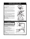
EMERSON QUICK START GUIDE
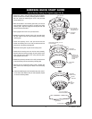
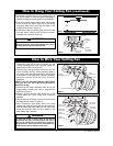
NOTE: Electric connections should be in accordance with the
National Electrical Codes and all Local Codes. Before
starting, disconnect power to the circuit at the fuse box or
circuit breaker panel.
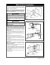
1. Remove the faceplate and screws from the existing wall switch.
Pull switch out from wall outlet box.
2. Disconnect wire from existing fan wall switch.
3. Slide the fan control in the OFF position (0).
4. Connect one BLACK wire from the fan control to the fan/motor
lead with a wire connector (provided).
5. Connect the other BLACK wire from the fan control to the
120VAC hot wire with a wire connector (provided).
NOTE: Use wire connectors (supplied) to secure electrical
connections.
6. Attach the fan control to the wall outlet box with two 6-32 x 3/4”
screws (provided).
7. Position the faceplate (provided) onto the speed control. Using
the two 6-32 x 1/4” screws, screw the faceplate and speed
control to the wall outlet box.
MOTOR LOAD
1.2 AMP MAXIMUM
TO 120VAC
SOURCE HOT
BLACK
BLACK
4
0
3
2
1
TO
NEUTRAL
TO FAN MOTOR LOAD
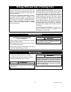
Installation of Wall Control (page 12)
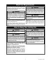
Turning off wall switch is not sufficient. To avoid possible electrical
shock, be sure electricity is turned off at the main fuse or circuit
breaker box before wiring. All wiring must be in accordance with
National and Local codes and the ceiling fan must be properly
grounded as a precaution against possible electrical shock.
!
WARNING
* For additional installation review full instructions on page 12.
5
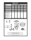
U.L. Model No.: CF905
SWITCH HOUSING
MOUNTING PLATE HOLE
1/4-20 x 9/16" CAPTIVE
FLANGE SCREW WITH
LOCKWASHER (2 sets
per flange)
BLADE FLANGE
ASSEMBLY
SWITCH HOUSING
MOUNTING SCREW (4)
SWITCH HOUSING
CONNECTOR
MOTOR CONNECTOR
SWITCH
HOUSING
ASSEMBLY
MOUNTING
SCREWS (4)
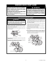
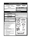
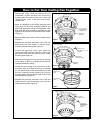
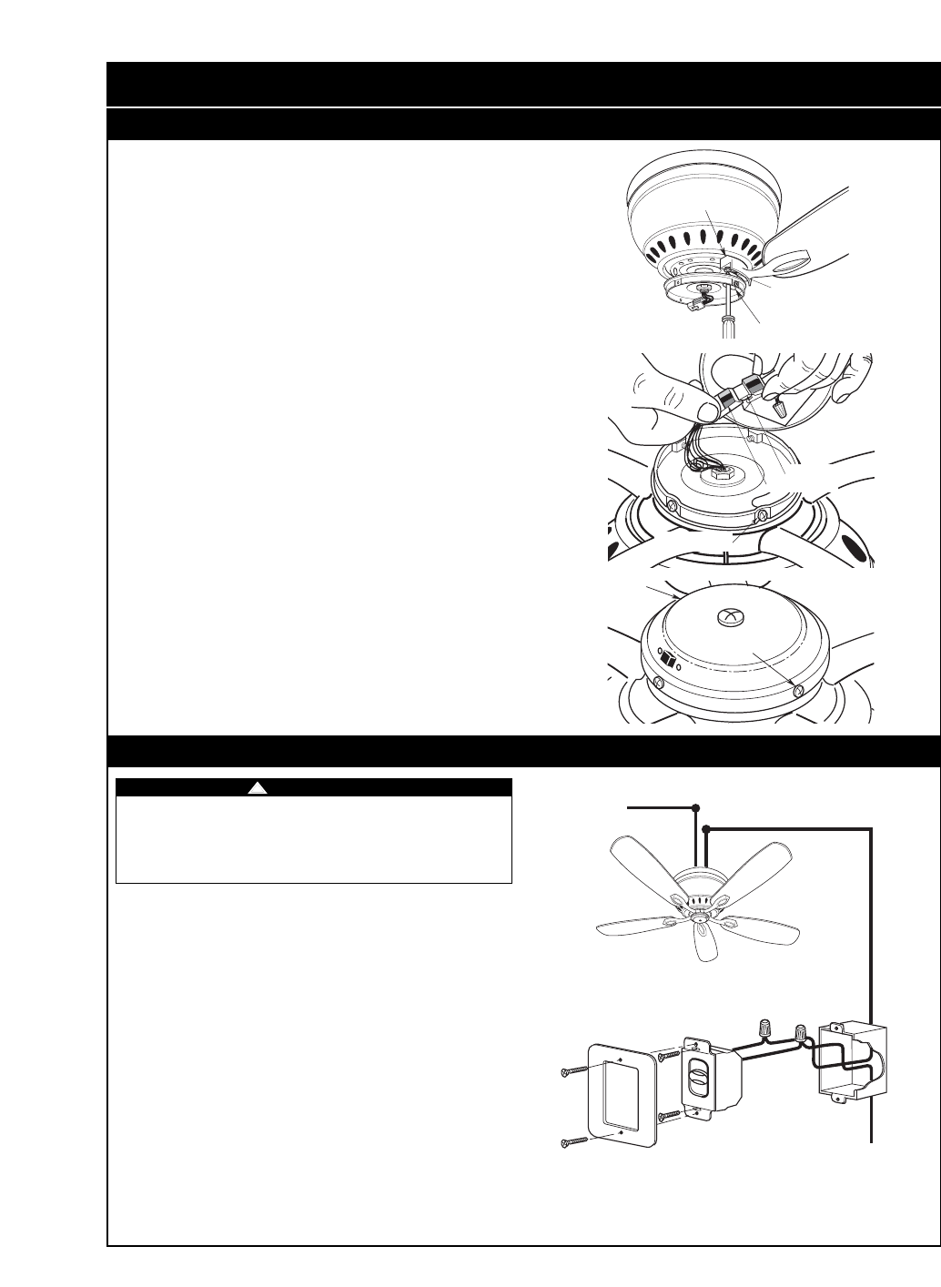
11. Attach one blade assembly to the motor using the two 1/4-20 x
9/16” captive flange screws with lockwashers. Make sure the
screws are tightened securely. Repeat this procedure for the
other four blade assemblies.
NOTE: Take care not to scratch the fan housing when installing
the blade assemblies.
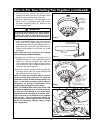
12. Remove the four switch housing assembly mounting screws
from the switch housing plate and retain for future use.
13. Engage the connector of the switch housing assembly with the
fan motor assembly connector. The two connectors are keyed
and color-coded and must be mated correctly (color-to-color)
before they can be engaged. Make sure the connector latch
closes properly.
14. Position the switch housing assembly on the switch housing
plate and align the holes in the switch housing assembly with
the holes in the plate. Secure the switch housing assembly by
installing the four screws removed previously.
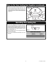
NOTE: To install an accessory light kit, remove switch housing
and make light kit electrical connections to blue and white leads
marked “For Light” in the switch housing. Follow light kit
instructions for wiring and installation. Then reinstall switch
housing as outlined above.
See page 10 for detailed instruction of how to connect the blue
fan wire to the branch circuit.