


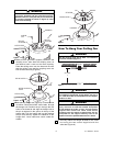
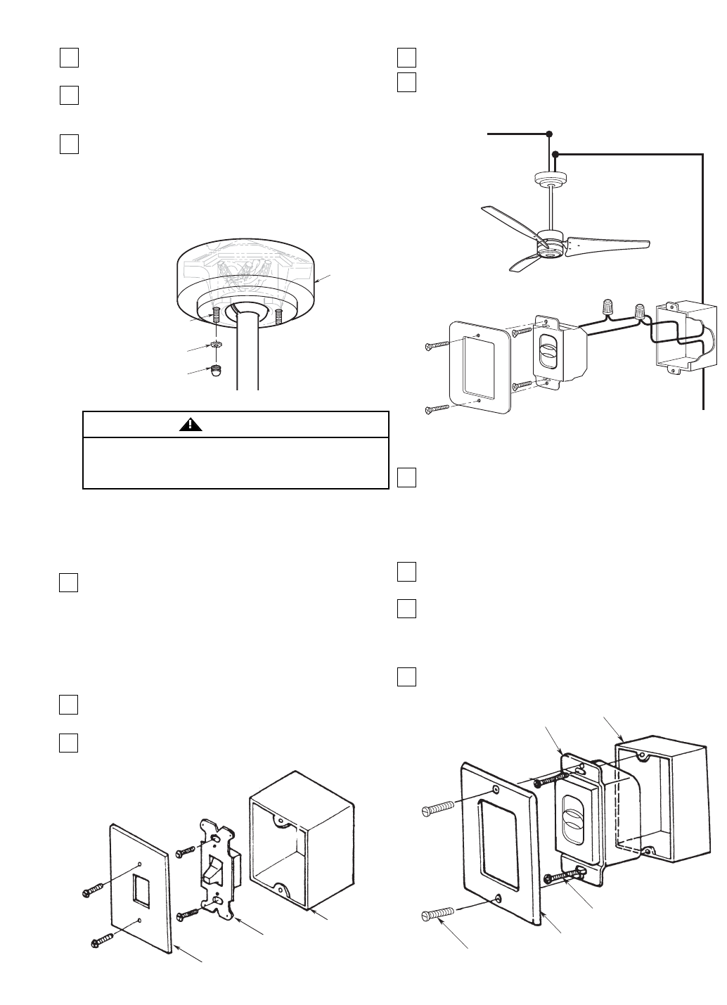
THREADED
STUDS (2)
#8 LOCKWASHER
KNURLED KNOB
CEILING
COVER
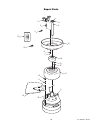
To avoid possible fire or shock, make sure that the
electrical wires are completely inside the outlet box and
not pinched between the ceiling cover and the ceiling.
WARNING
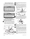
Figure 11
U.L. Model No.: CF765
7
3. Screw the two 1-1/4” threaded studs (supplied) into
the tapped holes in the hanger bracket (Figure 11).
4. Lift the ceiling cover up to the threaded studs and
turn until studs protrude through the holes in the
ceiling cover (Figure 11).
5. Secure the ceiling cover in place by sliding
lockwashers over the threaded studs and installing
the two knurled knobs (supplied) (Figure 11).
Tighten the knurled knobs securely until the ceiling
cover fits snugly against the ceiling. Your fan is now
wired to be turned on and off from the wall switch.
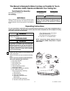
General
This control is designed to operate only one ceiling
fan
6. Before disconnecting power, ensure that the fan is
set at the highest speed.
NOTE: Electric connections should be in
accordance with the National Electrical Codes and
all Local Codes. Before starting, disconnect
power to the circuit at the fuse box or circuit
breaker panel.
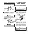
7. Remove the faceplate and screws from the existing
wall switch. Pull switch out from wall outlet box.
8. Disconnect wire from existing fan wall switch
(Figure 12).
FACEPLATE
SWITCH
WALL
OUTLET
BOX
Figure 12
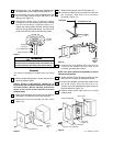
9. Slide the Fan Control to the OFF position (0).
10. Connect one BLACK wire from the Fan Control to
the fan/motor lead with a wire connector
(provided). (Figure 13.)
TO NEUTRAL
TO FAN MOTOR LOAD
TO
120VAC
SOURCE
HOT
BLACK
BLACK
4
0
3
2
1
Figure 13
11. Connect the other BLACK wire from the Fan
Control to the 120VAC hot wire with a wire
connector (provided with control).
NOTE: Use wire connectors (supplied) to secure
electrical connections.
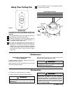
12. Attach the Fan Control to the wall outlet box with
two 6-32 x 3/4” screws (provided with control).
13. Position the faceplate (provided with control) onto
the speed control. Using the two 6-32 x 1/4”
screws, screw the faceplate and speed control to
the wall outlet box (Figure 14).
14. Restore power at the main fuse box or circuit
breaker panel.
6-32 x 1/4" SCREW (2)
FACEPLATE
SW46 FAN CONTROL
OUTLET BOX
4
0
3
2
1
6-32 x 3/4"
SCREW (2)
Figure 14