


4
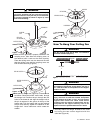
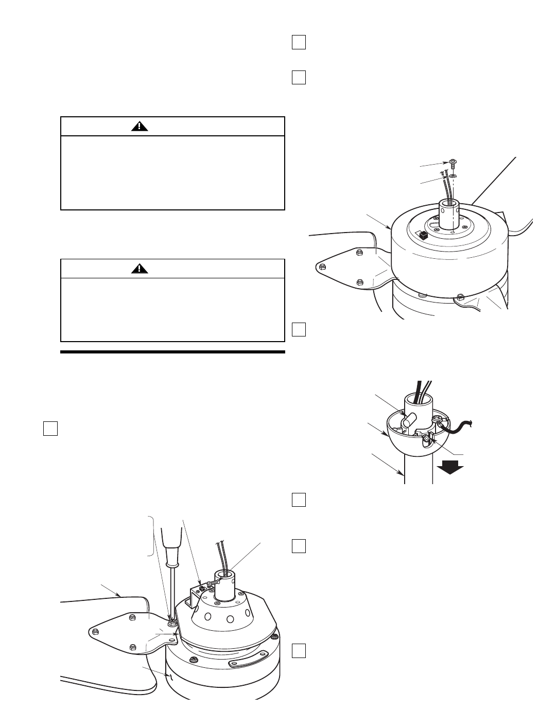
2. Remove the two setscrews from the top of the
motor coupler (Figure 1). Retain the setscrews for
future use.
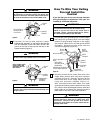
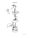
3. Route the two 80” motor leads through the center
hole in the motor cover. Place the motor cover over
the motor by aligning the reversing switch hole in
the cover over the reversing switch as shown in
Figure 2. Secure by installing three M5 x 10mm
pan head screws and three M5 external tooth
lockwashers (supplied) (Figure 2).
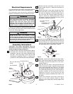
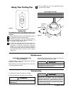
4. Remove the hanger ball by loosening the setscrew
in the hanger ball until the ball falls freely down the
downrod (Figure 3). Remove the pin from the
downrod, then remove the hanger ball. Retain the
pin and hanger ball for reinstallation in Step 9.
5. Separate, untwist and unkink the two motor leads,
then route them through the hanger ball/downrod
assembly and seat the downrod in the motor
coupler (Figure 4).
6. Align the clevis pin holes in the downrod with the
holes in the motor coupler. Install the clevis pin and
secure with the hairpin clip (Figure 4). The clevis
pin must go through the holes in the motor coupler
It is critical that the clevis pin in the motor coupler is
properly installed and the setscrews securely
tightened. Failure to verify that the pin and
setscrews are properly installed could result in the
fan falling.
7. Install two setscrews (previously removed in
Step 2) in the motor coupler (Figure 4). While
pulling up on the hanger ball, securely tighten both
setscrews.
MOTOR COVER
M5 EXTERNAL TOOTH
LOCKWASHER (3)
M5 x 10mm PAN HEAD
SCREW (3)
Figure 2
PIN
HANGER
BALL
SETSCREW
DOWNROD
Figure 3
Assembly Instructions
CAUTION: The blade assemblies must be
mounted on the motor assembly so that the
raised lip edge is facing up (Figure 1).
1. Rotate the motor hub so the notched area is above
the screw hole in the motor hub. Install one blade
assembly on the top of the motor assembly using
two M6 x 12mm pan head screws and two M6
lockwashers (supplied) (Figure 1). Repeat this
procedure for the remaining two blade assemblies.
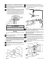
Electrical Requirements
If your fan is to replace an existing ceiling light fixture,
turn electricity off at the main fuse box at this time and
remove the existing light fixture.
Your new ceiling fan will require a grounded electrical
supply line of 120 volts AC, 60 Hz, 15 amp circuit.
The outlet box must be securely anchored and
capable of withstanding a load of at least 50 pounds.
To reduce the risk of fire, electric shock, or personal
injury, mount fan to outlet box marked “Acceptable
for Fan Support of 50 lbs. or less”, and use screws
supplied with outlet box. Most outlet boxes
commonly used for support of light fixtures are not
acceptable for fan support and may need to be
replaced. Consult a qualified electrician if in doubt.
WARNING
Turning off wall switch is not sufficient. To avoid
possible electrical shock, be sure electricity is turned
off at the main fuse box before wiring. All wiring must
be in accordance with National and Local codes and
the ceiling fan must be properly grounded as a
precaution against possible electrical shock.
WARNING
Figure 1
M6 x 12mm PAN HEAD
SCREW
M6 LOCKWASHER
REMOVE
SETSCREW (2)
REVERSING SWITCH
MOTOR ASSEMBLY
FLAT AREA OF
MOTOR HUB
BLADE
ASSEMBLY
U.L. Model No.: CF765