


6
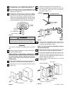
1. Connect the green grounding wire from the hanger
ball, the green grounding wire from the hanger
bracket to the grounding conductor of the supply
(this may be a bare wire or wire with green colored
insulation). Securely connect wires with wire
connectors (supplied) (Figure 10).
2. Securely connect the fan motor white wire to the
supply white (neutral) wire using wire connector
supplied (Figure 10). Securely connect the fan
motor black wire to the supply black (hot) wire
using wire connector supplied (Figure 10).
After connections have been made, turn leads
upward and carefully push the leads into the outlet
box, with the wires spread apart and the white and
green leads on one side of the outlet box and the
black leads on the other side of the outlet box.
THREADED
STUD (2)
HANGER
BRACKET
WHITE
SUPPLY
(NEUTRAL)
GREEN WIRE (GROUND)
FROM HANGER BRACKET
LISTED WIRE
CONNECTOR (3)
SUPPLY GROUND
WIRE
GREEN WIRE
(GROUND) FROM
HANGER BALL
BLACK FAN WIRE
BLACK
SUPPLY
(HOT)
WHITE
FAN WIRE
Figure 10
Check to see that all connections are tight, including
ground, and that no bare wire is visible at the wire
connectors, except for the ground wire. Do not
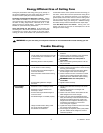
operate fan until blades are in place. Noise and fan
damage could result.
WARNING
U.L. Model No.: CF765
To avoid possible electrical shock, be sure electricity
is turned off at the main fuse box before wiring.
NOTE: If you are not sure if the outlet box is
grounded, contact a licensed electrician for advice,
as it must be grounded for safe operation.
WARNING
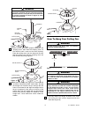
How To Wire Your Ceiling
Fan and Install the
Control
If you feel that you do not have enough electrical
wiring knowledge or experience, have your fan
installed by a licensed electrician.
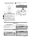
Hanger bracket must seat firmly against outlet box. If
the outlet box is recessed, remove wall board until
bracket contacts box. If bracket and/or outlet box are
not securely attached, the fan could wobble or fall.
WARNING
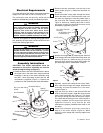
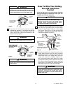
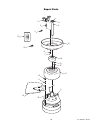
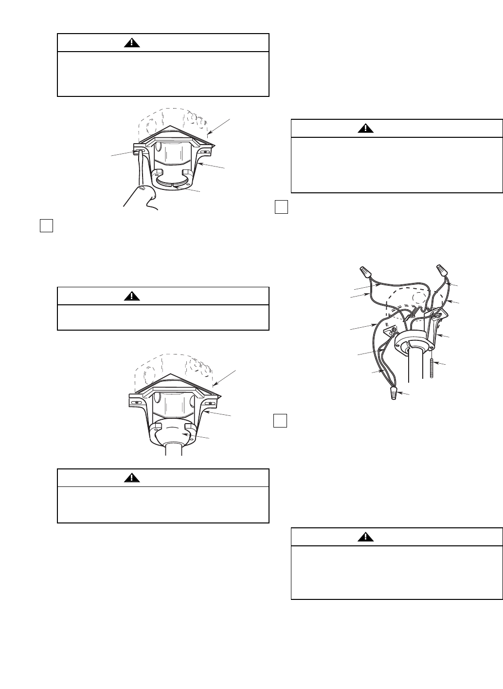
2. Carefully lift the fan and seat the hanger
ball/downrod assembly on the hanger bracket that
was just attached to the outlet box. Be sure the
groove in the ball is lined up with the tab on the
hanger bracket (Figure 9).
TWO SCREWS
SUPPLIED WITH
OUTLET BOX
HANGER
BRACKET
TAB
OUTLET
BOX
Figure 8
OUTLET
BOX
HANGER
BRACKET
HANGER BALL/
DOWNROD
ASSEMBLY
NOTE: CEILING COVER,
SUPPLY WIRES AND
FAN WIRES OMITTED
FOR CLARITY.
Figure 9
Failure to seat tab in groove could cause damage to
electrical wires and possible shock or fire hazard.
WARNING
To avoid possible fire or shock, do not pinch wires
between the hanger ball/downrod assembly and
hanger bracket.
WARNING