


7
If you feel that you do not have enough electrical
wiring knowledge or experience, have your fan
installed by a licensed electrician.
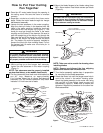
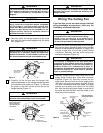
1. Connect the green grounding lead from the hanger
ball and the green grounding lead from the hanger
bracket to the grounding conductor of supply (this
may be a bare wire or wire with green colored
insulation). Securely connect wires using wire
connectors supplied (Figure 12).
2. Securely connect the fan motor white wire to the
supply white (neutral) wire using wire connector
supplied (Figure 12). Securely connect the fan
motor black wire and blue wire to the supply black
(hot) wire using wire connector supplied (Figure
12). After connections have been made, turn leads
upward and carefully push leads into the outlet
box, with the white and green leads on one side of
the outlet box and the black and blue leads on the
other side of the outlet box.
Wiring The Ceiling Fan
To avoid possible electrical shock, be sure electricity
is turned off at the main fuse box before wiring.
NOTE: If you are not sure if the outlet box is
grounded, contact a licensed electrician for advice,
as it must be grounded for safe operation.
WARNING
!
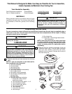
U.L. Model No.: CF701
Hanger bracket must seat firmly against outlet box. If
the outlet box is recessed, remove wall board until
bracket contacts box. If bracket and/or outlet box are
not securely attached, the fan could wobble or fall.
WARNING
!
To reduce the risk of fire, electric shock, or personal
injury, mount fan to outlet box marked “Acceptable
for Fan Support”, and use screws supplied with
outlet box. Most outlet boxes commonly used for
support of light fixtures are not acceptable for fan
support and may need to be replaced. Consult a
qualified electrician if in doubt.
WARNING
!
The outlet box and joist must be securely mounted
and capable of supporting at least 50 lbs. Use only a
U.L. outlet box listed as “Acceptable for Fan
Support”.
WARNING
!
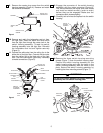
OUTLET
BOX
HANGER
BRACKET
HANGER BALL/
DOWNROD ASSEMBLY
Figure 3
NOTE: CEILING COVER,
SUPPLY WIRES AND
FAN WIRES OMITTED
FOR CLARITY.
Figure 11
Failure to seat tab in groove could cause damage to
electrical wires and possible shock or fire hazard.
WARNING
!
To avoid possible fire or shock, do not pinch wires
between the hanger ball/downrod assembly and
hanger bracket.
WARNING
!
TWO SCREWS
SUPPLIED WITH
OUTLET BOX
HANGER
BRACKET
TAB
OUTLET
BOX
Figure 2
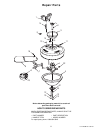
Figure 10
1. Securely attach the hanger bracket to the outlet
box using the two screws supplied with the outlet
box. (Figure 10.)
2. Carefully lift the fan and seat the hanger ball/
downrod assembly on the hanger bracket that was
just attached to the outlet box (Figure 11). Be sure
the groove in the ball is lined up with tab on the
hanger bracket (Figure 11).
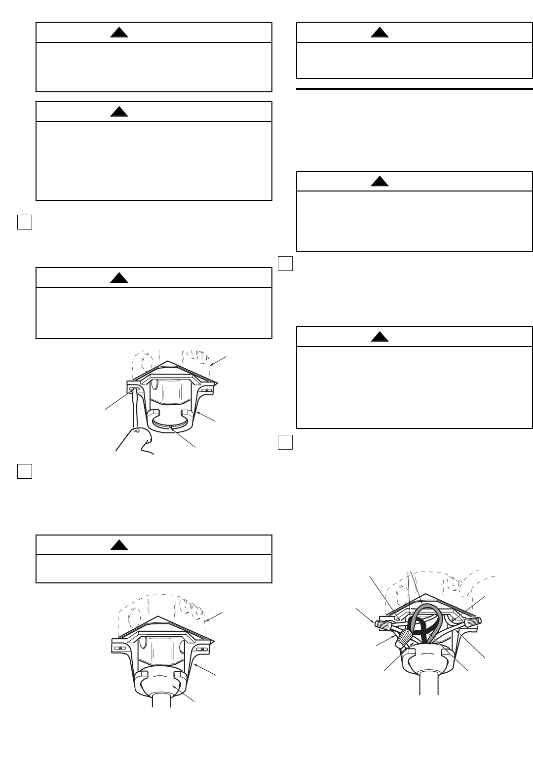
GROUND
WIRE
LISTED
WIRE
CONNECTOR (3)
GREEN WIRE
(GROUND) FROM
HANGER BRACKET
GREEN WIRE
(GROUND) FROM
HANGER BALL
WHITE SUPPLY
(NEUTRAL)
WHITE FAN
WIRE
BLACK SUPPLY
(HOT)
BLACK AND BLUE
FAN WIRES
Figure 12
NOTE: CEILING COVER
OMITTED FOR CLARITY.
This product is designed to use only those parts
supplied with this product and/or any accessories
designated specifically for use with this product by
Emerson Electric Co. Substitution of parts or
accessories not designated for use with this product
by Emerson Electric Co. could result in personal
injury or property damage.
WARNING
!