


5
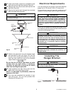
U.L. Model No.: CF701
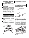
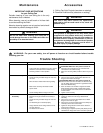
SWITCH
HOUSING
ASSEMBLY
SWITCH HOUSING
CONNECTOR
MOTOR CONNECTOR
SWITCH HOUSING
MOUNTING SCREW
Figure 6
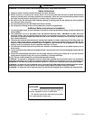
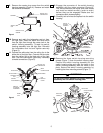
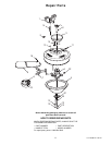
9. Remove the center plug screw from the switch
housing assembly (Figure 4). Remove and retain
the two wire connectors.
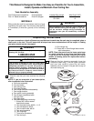
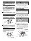
10. Remove and retain the lockwasher and nut from
the light fitter. Insert the black and white wires
from the light fitter through the center hole in the
switch housing assembly. Thread the switch
housing assembly onto the light fitter. Reinstall
the lockwasher and nut and tighten securely
(Figure 5).
11. Connect the white wire from the ceiling fan to the
white wire of the light fitter. Connect the blue wire
from the ceiling fan to the black wire of the light
fitter. Use wire connectors (previously removed)
to make connections (Figure 5).
SCREWS
CENTER PLUG
SCREW
SWITCH
CUP
SWITCH CUP
CONNECTOR
Figure 4
SPRING
LOCKWASHER
SCREWS
SWITCH CUP
CONNECTOR
WIRE
CONNECTORS
WHITE WIRES
SWITCH
HOUSING
ASSEMBLY
BLACK WIRE
NUT
FAN
SWITCH
CHAIN
BLUE WIRE
LIGHT
FITTER
BOWL
CAP
Figure 5
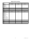
12. Engage the connector of the switch housing
assembly with the motor connector (Figure 6).
The two connectors are keyed and color-coded
and must be mated correctly (color-to-color)
before they can be engaged. Make sure the
connectors latch closes properly.
13. Carefully tuck all wires and splices into the switch
housing.
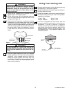
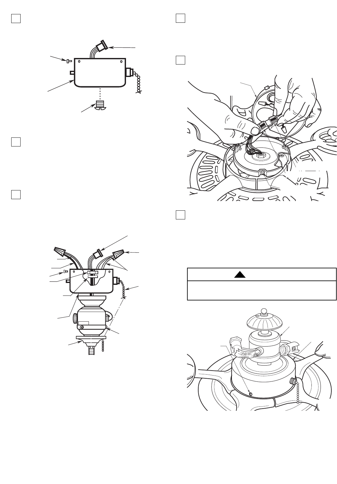
14.Remove the three switch housing mounting
screws (Figure 7) from the switch housing plate.
Position the switch housing assembly on the
switch housing plate and align the holes in the
switch housing assembly with the holes in the
plate. Secure the switch housing assembly by
installing the three mounting screws (Figure 7).
Do not pinch wires between the switch housing
assembly and the switch housing plate.
WARNING
!
MOUNTING
SCREWS (3)
SWITCH HOUSING
ASSEMBLY
LIGHT FITTER
Figure 7