


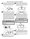
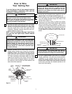

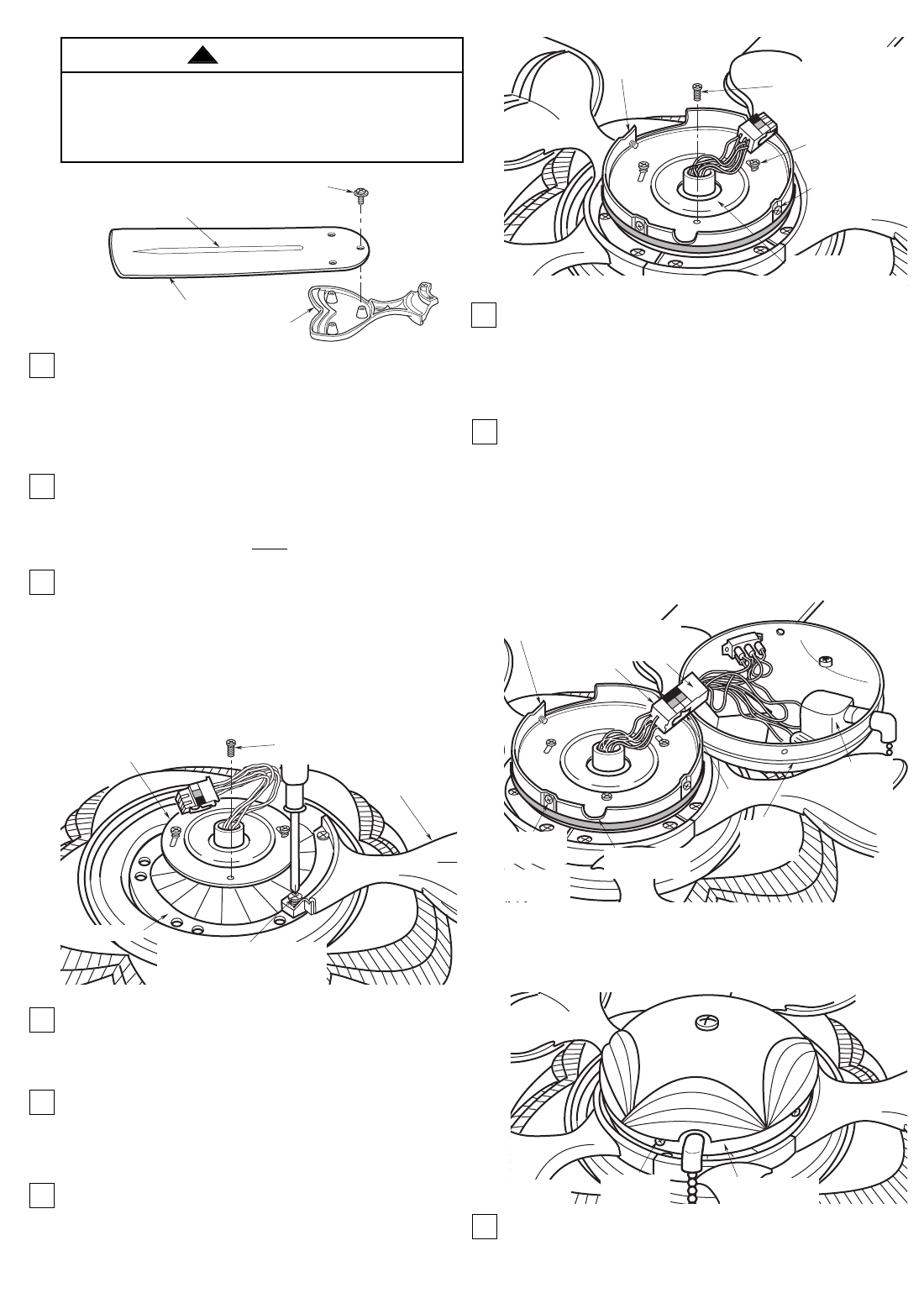
14. Engage the connector of the switch housing
assembly with the motor connector (Figure 8).
The two connectors are keyed and color-coded
and must be mated correctly (color-to-color)
before they can be engaged. Make sure the
connector latch closes properly.
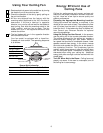
15. Remove the four mounting screws from the
bracket switch housing assembly with rubber
cover (Figure 8). Position the switch housing
assembly on the bracket switch housing
assembly with rubber cover and secure using the
four mounting screws (Figure 9).
NOTE: Do not pinch wires between the switch
housing assembly and the bracket switch
housing assembly with rubber cover.
NOTE: The switch housing assembly must be
oriented so that the pull chain switch will fit into
the rounded slot (Figure 8) in the bracket switch
housing assembly with rubber cover.
16. You have now completed the assembly of your
new ceiling fan. You can now proceed with
hanging and wiring your fan.
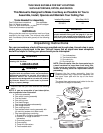
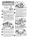
8. Turn the fan motor assembly upside down in
preparation for mounting the fan blade assemblies.
NOTE: Remove and discard the five shipping
spacers and screws from the motor hub.
NOTE: Take care not to scratch fan housing when
installing blades.
9. Loosely attach one blade assembly to the motor
hub using two M6 x 14 flange screws with lock-
washers preassembled in flange (Figure 6). Make
sure the screws are NOT tightened. Repeat this
procedure for the other four blade assemblies.
10. The blade flanges have an interlocking feature
that must be fully engaged before tightening the
screws. Make sure all the flanges are properly
engaged and then tighten the flange screws.
If one of the flanges does not seat properly on the
motor hub, loosen the adjacent flange screws,
re-engage and reseat the flanges, then tighten the
screws again.
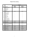
11. Remove and retain one of the three serrated head
screws from the adaptor plate (Figure 6). Loosen
the other two serrated head screws, three or four
turns.
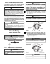
12. Position the bracket switch housing assembly with
rubber cover on the adaptor plate so that the two
screws mate with the two keyhole slots in the
bracket switch housing assembly with rubber
cover.
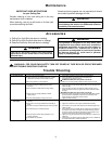
13. Turn the bracket switch housing assembly with
rubber cover clockwise and tighten both screws
(Figure 7). Reinstall the other serrated head
screw in the remaining hole in the bracket switch
housing assembly with rubber cover.
5
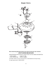
FAN BLADE
BLADE FLANGE
M5 x 6 WASHER HEAD SCREW (3)
RIB LINE
(THIS SIDE OF BLADE UP)
Figure 5
BLADE FLANGE
ADAPTOR
PLATE
MOTOR HUB
M6 x 14 FLANGE SCREWS WITH
LOCKWASHERS (PREASSEMBLED
IN FLANGE)
REMOVE ONE SERRATED
HEAD SCREW
Figure 6
MOUNTING
SCREWS (4)
BRACKET SWITCH
HOUSING ASSEMBLY
WITH RUBBER COVER
REINSTALL ONE
SERRATED HEAD
SCREW
TIGHTEN TWO PAN
HEAD SCREWS
ADAPTOR PLATE
Figure 7
MOUNTING
SCREWS (4)
SWITCH HOUSING
ASSEMBLY
Figure 9
To reduce the risk of personal injury, do not bend the
blade flange when installing the blade flanges,
balancing the blades or cleaning the fan. Do not
insert foreign objects in between rotating fan blades.
WARNING
!
SLOT FOR PULL
CHAIN SWITCH
LATCH
MOTOR
CONNECTOR
SWITCH
HOUSING
CONNECTOR
SWITCH
HOUSING
ASSEMBLY
BRACKET SWITCH
HOUSING ASSEMBLY
WITH RUBBER COVER
PULL
CHAIN
SWITCH
MOUNTING
SCREWS (4)
Figure 8