U.L. Model No.: CF3300
How to Put Your Ceiling Fan Together
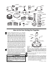
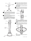
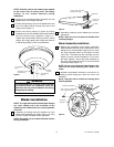
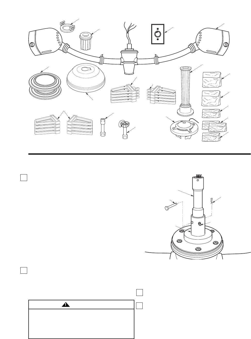
HAIRPIN
CLIP
CLEVIS PIN
DOWNROD
COUPLING
DOWNROD
EXTENSION
5/16-18 x 1/4" CUP
POINT SETSCREW (2)
Figure 1
4
OFF
K. HANGER BRACKET
ASSEMBLY
M. SW22
WALL
CONTROL
A. FAN
ASSEMBLY
B. FAN MOTOR
COVERS (2)
H. RIGHT HAND
BLADE FLANGES (4)
C. DECORATIVE DOWNROD
SLEEVE ASSEMBLY
G. CEILING
CANOPY
M. MOUNTING
BRACKET BAG
N. HARDWARE
BAG
O. FLANGE
ASSEMBLY
BAG
P. BLADE
ASSEMBLY
BAGS
Q. DOWNROD
ASSEMBLY
BAG
F. DECORATIVE
STRAP RING
D. UPPER
DECORATIVE
DOWNROD SLEEVE
I. LEFT HAND BLADE
FLANGES (4)
L. BLADE
MEDALLIONS (8)
E. DOWNROD
EXTENSION
J. HANGER BALL/
DOWNROD
EXTENSION
1. Loosely install both 5/16-18 x 1/4” cup point
setscrews (supplied) into the downrod coupling.
Separate, untwist and unkink the three 80” motor
leads and support wire. Route the motor lead wires
and support wire through the downrod extension.
Align the clevis pin holes in the downrod extension
with the holes in the downrod coupling. Install the
clevis pin and secure with the hairpin clip
(Figure 1). The clevis pin must go through the
holes in the downrod coupling and the holes in the
downrod extension. Be sure to push the straight leg
of the hairpin clip through the hole near the end of
the clevis pin until the curved portion of the hairpin
clip snaps around the clevis pin. The hairpin clip
must be properly installed to prevent the clevis pin
from working loose. Pull on the downrod extension
to make sure the clevis pin is properly installed.
2. While pulling up on the downrod extension,
securely tighten the two setscrews in the downrod
coupling using the 3/16” hex wrench (supplied).
The setscrews must be tightened into the downrod
extension. A loose extension downrod will result
with fan assembly noise and vibration.
It is critical that the clevis pin in the downrod
coupling is properly installed and the
setscrews securely tightened. Failure to verify
that the pin and setscrews are properly
installed (as shown in Figure 1) could result in
the fan falling.
WARNING
NOTE: For ease of installation, loosely tape the
ends of the motor leads and the support wire
together to route through downrod during fan
installation.
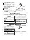
3. Route the motor leads and support wire through
the downrod (Figure 2).
4. Securely attach the downrod to the downrod
extension using the four 1/4 x 10mm round head
screws (supplied in the downrod assembly bag).
The round head screws must be fully tightened into
the downrod extension. A loose downrod will result
with fan assembly noise and vibration.


