


6
UL Model No.: CF244 & CF252
11. Carefully turn the partially assembled
ceiling fan right side up and place the
fan securely into the packing
styrofoam in preparation for final
assembly.
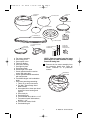
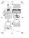
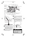
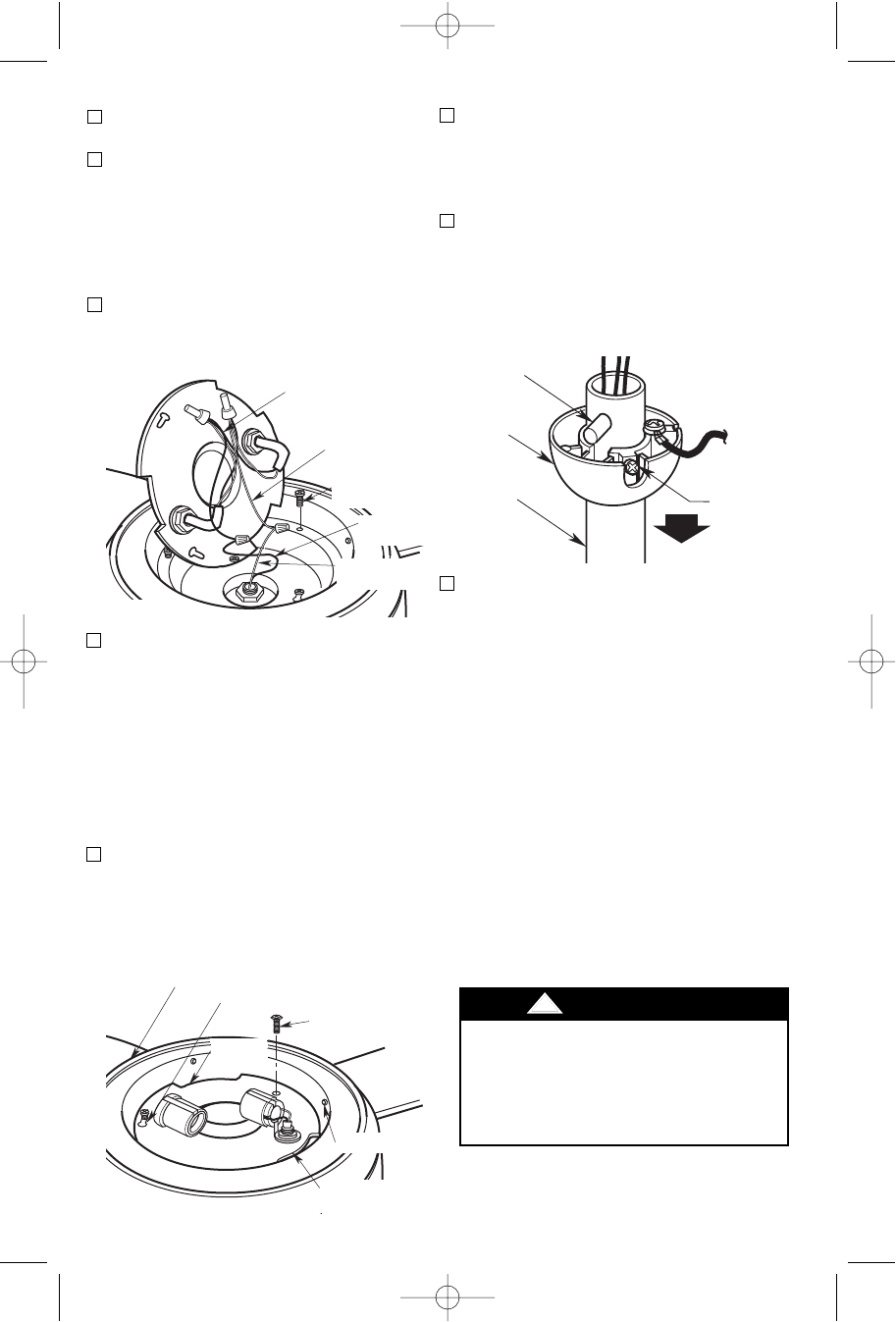
12. Remove the hanger ball by loosening
the setscrew in the hanger ball until
the ball falls freely down the downrod
(Figure 5). Remove the pin from the
downrod, then remove the hanger
ball. Retain the pin and hanger ball for
reinstallation in Step 16.
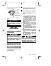
13. Loosen setscrew in motor coupler if
necessary. Separate, untwist and
unkink the three 80” motor leads.
Route the motor lead wires through
the downrod. Align the clevis pin
holes in the downrod with the holes in
the motor coupler. Install the clevis
pin and secure with the hairpin clip
(Figure 6). The clevis pin must go
through the holes in the motor coupler
and the holes in the downrod. Be sure
to push the straight leg of the hairpin
clip through the hole near the end of
the clevis pin until the curved portion
of the hairpin clip snaps around the
clevis pin. The hairpin clip must be
properly installed to prevent the clevis
pin from working loose. Pull on the
downrod to make sure the clevis pin is
properly installed.
PIN
HANGER
BALL
SETSCREW
DOWNROD
Figure 5
It is critical that the clevis pin in the motor
coupler is properly installed and the
setscrew securely tightened. Failure to
verify that the pin and setscrew are
properly installed (as shown in Figure 6)
could result in the fan falling.
!
WARNING
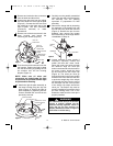
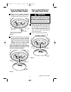
9. Tuck the wires and connectors into the
fan housing. Position the light kit plate
into the fan housing by placing the cut
out notches over the fan housing
dimples (Figure 4).
10. Attach the light kit plate assembly to
the lower housing using two key slot
holes (Figure 4). Secure the light kit
plate assembly by tightening the two
screws. Reinstall the screw that was
previously removed.
NOTE: Make sure all wires and
connectors are tucked under the light
kit plate and not pinched between light
kit plate and fan housing.
REMOVE M4 x 10mm
PAN HEAD SCREW
KEY HOLE SLOT (2)
LOWER HOUSING
LIGHT KIT
PLATE
DIMPLES
CUT OUT
NOTCHES
Figure 4
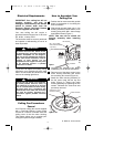
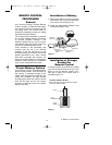
6. Remove and retain the wire connectors
from the white and blue wires.
7. Connect the wire wire from the ceiling
fan to the white wire of the light kit plate
(Figure 3). Connect the blue wire from
the ceiling fan to the black wire of the
light kit plate. Use wire connectors
(previously removed) to make
connections.
8. Remove one of the three screws in the
lower housing and loosen the
remaining two screws (Figure 3).
LIGHT KIT
BLACK WIRE
LIGHT KIT
WHITE WIRE
FAN MOTOR
WHITE WIRE
FAN MOTOR
BLUE WIRE
REMOVE ONE
LOWER HOUSING
SCREW
Figure 3
BP7408 44" & 52" Curva 1/12/10 8:52 AM Page 6