


4
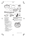
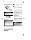
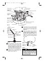
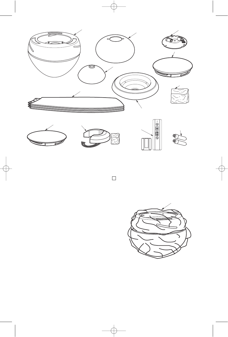
2. Remove the fan motor assembly from
the protective plastic bag. Place all
carton contents on a protective
surface.
D. FAN BLADES (3)
A. FAN MOTOR
ASSEMBLY
L. LOOSE
PARTS BAG
B. CEILING COVER
F. LIGHT KIT
PLATE
C. COUPLER COVER
K. 50W MINI
CANDELABRA
HALOGEN BULBS
E. LOWER HOUSING
I. 6-SPEED ELECTRONIC
RECEIVER
G. GLASS SHADE
H. NO-LIGHT
COVER PLATE
J. 6-SPEED HANDHELD
TRANSMITTER
NOTE: Place the parts from the loose
parts bags in a small container to keep
them from being lost.
PROTECTIVE
PLASTIC BAG
UL Model No.: CF244 & CF252
a. Fan motor assembly
b. One ceiling cover
c. One coupler cover
d. Three fan blades
e. One lower housing
f. One light kit plate
g. One glass shade
h. One no-light cover plate
i. One 6-speed electronic receiver
control with parts bag
j. One 6-speed handheld transmitter
with wall bracket
k. Two 50W halogen mini candelabra
bulbs
l. One loose parts bag containing:
1. Three 12 ga. wire connectors
2. Ten M5 x 16mm flange head
blade screws
3. One spare M4 x 10mm pan head
screws for lower housing and
light kit
4. One clevis pin
5. One hairpin clip
6. Two threaded stud, #8-32 x 1-1/4”
7. Two external tooth lockwashers,
#8-32 x 1-1/4”
8. Two knurled knobs, #8-32
9. One balancing kit
BP7408 44" & 52" Curva 1/12/10 8:52 AM Page 4