


UL Model No.: CF244 & CF252
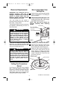
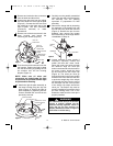
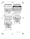
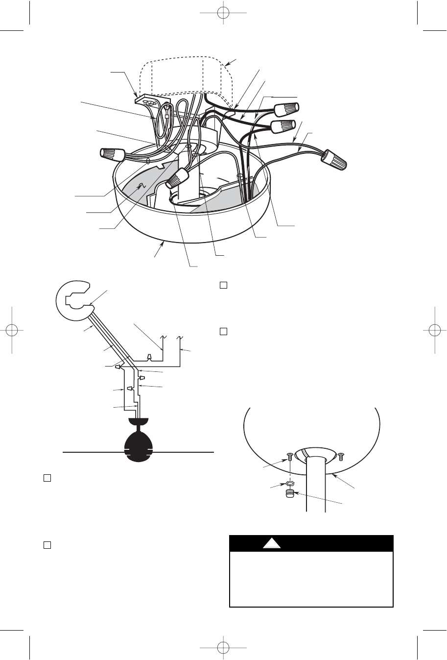
3. After connections have been made,
turn leads upward and carefully push
leads into the outlet box, with the white
and green leads on one side of the
outlet box and the black and blue leads
on the other inside of the outlet box.
4. Screw the two 1-1/4” threaded studs
(supplied) into the tapped holes in the
hanger bracket (Figure 11).
WHITE
SUPPLY
WIRE
BLACK FAN WIRE
RECEIVER
WHITE FAN WIRE
BLUE RECEIVER
WIRE
BLUE FAN WIRE
BLACK SUPPLY
WIRE
WHITE
RECEIVER
WIRE
BLACK RECEIVER
WIRE
BLACK/WHITE
RECEIVER WIRE
Figure 13
10
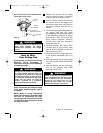
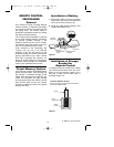
To avoid possible fire or shock, make
sure that the electrical wires are
completely inside the outlet box and
not pinched between the ceiling
cover and the ceiling.
!
WARNING
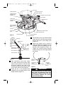
#8 EXTERNAL
TOOTH
LOCKWASHER (2)
CEILING
COVER
1-1/4"
THREADED
STUD (2)
#8-32 KNURLED
KNOB (2)
Figure 14
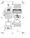
OUTLET BOX
BLACK SUPPLY WIRE
BLACK/WHITE RECEIVER WIRE
BLACK FAN WIRE
BLUE FAN WIRE
BLUE RECEIVER
WIRE
CEILING COVER
WHITE RECEIVER WIRE
WHITE FAN WIRE
WIRE CONNECTOR
RECEIVER
WHITE SUPPLY
WIRE
SUPPLY GROUND
WIRE (GREEN OR
BARE)
HANGER BALL
GROUND WIRE
(GREEN)
HANGER BRACKET
GROUND WIRE
(GREEN)
HANGER BRACKET
BLACK RECEIVER WIRE
OPEN
PORTION OF
RECEIVER
HERE
Figure 12
5. Lift the ceiling cover up to the threaded
studs and turn until the studs protrude
through the holes in the ceiling cover
(Figure 14).
6. Secure the ceiling cover in place by
sliding lockwashers (supplied) over the
threaded studs and installing the two
knurled knobs (supplied). (Figure 14).
Tighten the knurled knobs securely
until the ceiling cover fits snugly against
the ceiling.
BP7408 44" & 52" Curva 1/12/10 8:52 AM Page 10