


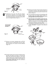
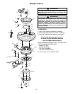
9. Install the setscrew (supplied in loose parts bag) in
the motor coupling and tighten using the 5/32"
setscrew wrench (supplied) (Figure 17).
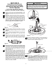
10.Screw two 1” threaded studs (provided) into the
motor (Figure 22). Leave approximately 7/8” of the
stud extending above the motor. Slide the motor
cover over the downrod and rotate the cover until
the threaded studs protrude; install two knurled
knobs (supplied) to secure the cover.
SETSCREW
CLEVIS PIN
MOTOR
COUPLING
DOWNROD
HAIRPIN
CLIP
MOTOR
COUPLING
HAIRPIN
CLIP
CLEVIS
PIN
DOWNROD
CONNECT YELLOW LEAD
TO YELLOW LEAD
CLEVIS
PIN
Figure 16
DOWNROD
SETSCREW
Figure 17
8
SECTION B
Assembly Instructions
for Installing the CF2300
Ceiling Fan with Any Other
Control Method
(excluding the SR120 Remote
Control or the SW140 Wall Control)
1. Position the fan motor and housing assembly in the
lower foam packing so that the top of the motor is fac-
ing you.
2. Separate, untwist and unkink the four motor leads.
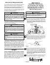
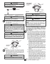
3. Obtain the hanger ball/downrod assembly and
remove the hanger ball by loosening the setscrew
in the hanger ball until the ball falls freely down the
downrod (Figure 14). Remove the pin from the
downrod , then remove the hanger ball. Retain the
pin and hanger ball for reinstallation in step 9.
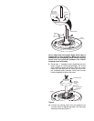
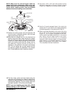
4. Push the uplight yellow lead assembly connector
through the downrod (Figure 15) until it extends
about 4”.
5. Cut the yellow lead approximately 3” from the end
of the pipe. Strip insulation 1/2” from end of the
wires.
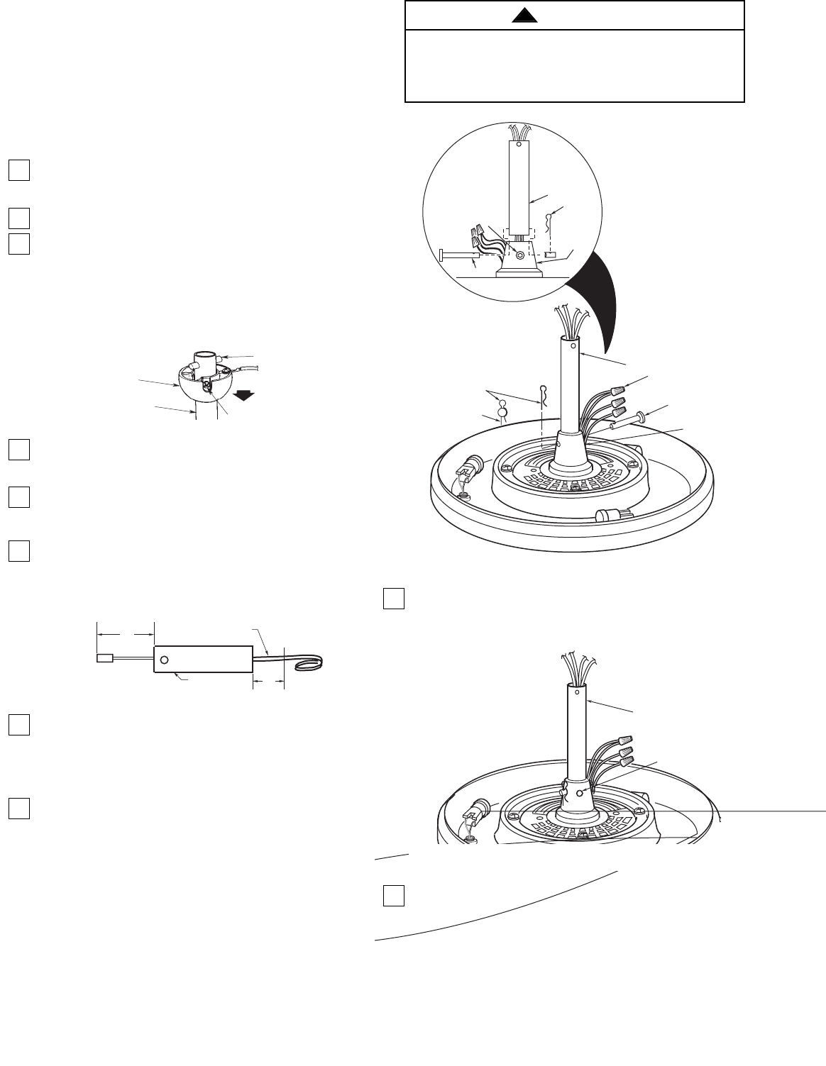
6. Using the wire connector supplied, connect the
uplight yellow lead assembly to the yellow lead
from the fan motor and housing assembly (Figure
16).
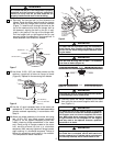
7. Route the white, blue, and black motor leads through
the downrod. Fold the yellow, red, and brown wires
into the slot in the motor coupling, slide the downrod
down the wires and seat the downrod in the motor
coupling (Figure 16).
8. Align the clevis pin holes in the downrod with the
holes in the motor coupling. Install the clevis pin and
secure with the hairpin clip (Figure 16). The clevis pin
must go through the holes in the motor coupling and
the holes in the downrod . Push the straight leg of the
hairpin clip through the hole near the end of the cle-
vis pin until the curved portion of the hairpin clip
snaps around the clevis pin. The hairpin clip must be
properly installed to prevent the clevis pin from work-
ing loose. Pull on the hanger ball to make sure the
clevis pin is properly installed.
HANGER BALL
DOWNROD
CLEVIS PIN
SETSCREW
Figure 14
4"
DOWNROD
CUT
HERE
3"
UPLIGHT YELLOW
LEAD ASSEMBLY
Figure 15
It is critical that the clevis pin in the motor coupling
is properly installed and the setscrew securely tight-
ened. Failure to verify that the pin and setscrew are
properly installed could result in the fan falling.
WARNING
!