


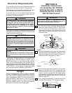
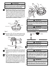
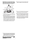

17. Securely attach the hanger bracket to the outlet
box using the two screws supplied with the outlet
box (Figure 23).
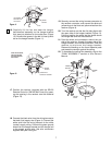
18. Carefully lift the fan and seat the hanger
ball/downrod assembly on the hanger bracket that
was just attached to the outlet box (Figure 24). Be
sure the groove in the ball is lined up with tab on
the hanger bracket (Figure 23).
NOTE: If you are installing a SR120 Remote
Control or a SW140 Wall Control to operate the
fan and light, refer to the installation instructions
and wiring diagrams shown in Section A of this
Owner’s Manual.
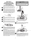
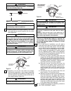
19. For a wall control installation you will need a
three-wire (with ground) conductor cable between
the ceiling and wall outlet boxes. This will allow
you to control the fan separately from the lights.
Figure 25 is a basic wiring diagram that will con-
trol the uplight and downlight on a switch and the
fan on a separate control. Refer to the installation
instructions and wiring diagrams supplied with the
Emerson Fan Control Owner’s Manual.
a. Connect the green grounding lead from the
hanger ball and the green grounding lead from
the hanger bracket to the grounding conductor
of supply (this may be a bare wire or a wire
with green colored insulation). Securely con-
nect wires with wire connector supplied.
b. Securely connect the white wire from the
downrod to the supply white (neutral) wire
using wire connector supplied. Securely con-
nect the black wire from the downrod to the
supply black (hot) wire using wire connector
supplied.
c. Cut terminal off of the yellow lead wire and
strip insulation 1/2” from end of wire.
d. Securely connect the blue wire and yellow wire
from the downrod to the supply red (hot) wire
using wire connector (supplied). After connec-
tions have been made, turn leads upward and
carefully push leads into the outlet box, with
the white and green leads on one side of the
outlet box and the black, blue and yellow leads
on the other side of the outlet box.
20. To complete the ceiling fan assembly, proceed to
the “FINAL ASSEMBLY” section.
10
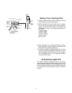
CEILING
FLOOR
AT LEAST
7'
Figure 22
TWO SCREWS
SUPPLIED WITH
OUTLET BOX
HANGER
BRACKET
TAB
OUTLET
BOX
OUTLET
BOX
HANGER
BRACKET
HANGER BALL/
DOWNROD ASSEMBLY
NOTE: CEILING COVER,
SUPPLY WIRES AND
FAN WIRES OMITTED
FOR CLARITY.
Figure 23
Figure 24
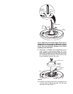
The fan must be hung with at least 7' of clearance
from floor to blades (Figure 22).
WARNING
!
The outlet box must be securely anchored and capable
of withstanding a load of at least 50 lbs.
WARNING
!
To reduce the risk of fire, electric shock, or personal
injury, mount fan to outlet box marked acceptable for
fan support, and use screws supplied with outlet
box. Most outlet boxes commonly used for support
of light fixtures are not acceptable for fan support
and may need to be replaced. Consult a qualified
electrician in in doubt.
WARNING
!
Hanger bracket must seat firmly against outlet box. If
the outlet box is recessed, remove wall board until
bracket contacts box. If bracket and/or outlet box are
not securely attached, the fan could wobble or fall.
WARNING
!
Failure to seat tab in groove could cause damage to
electrical wires and possible shock or fire hazard.
WARNING
!
To avoid possible fire or shock, do not pinch wires
between the hanger ball/downrod assembly and
hanger bracket.
WARNING
!
To avoid possible fire or shock, be sure that
electricity is turned off at the main fuse box before
wiring.
NOTE: If you are not sure if the outlet box is
grounded, contact a licensed electrician for advice,
as it must be grounded for safe operation.
WARNING
!