


7
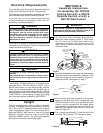
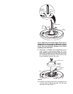
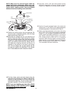
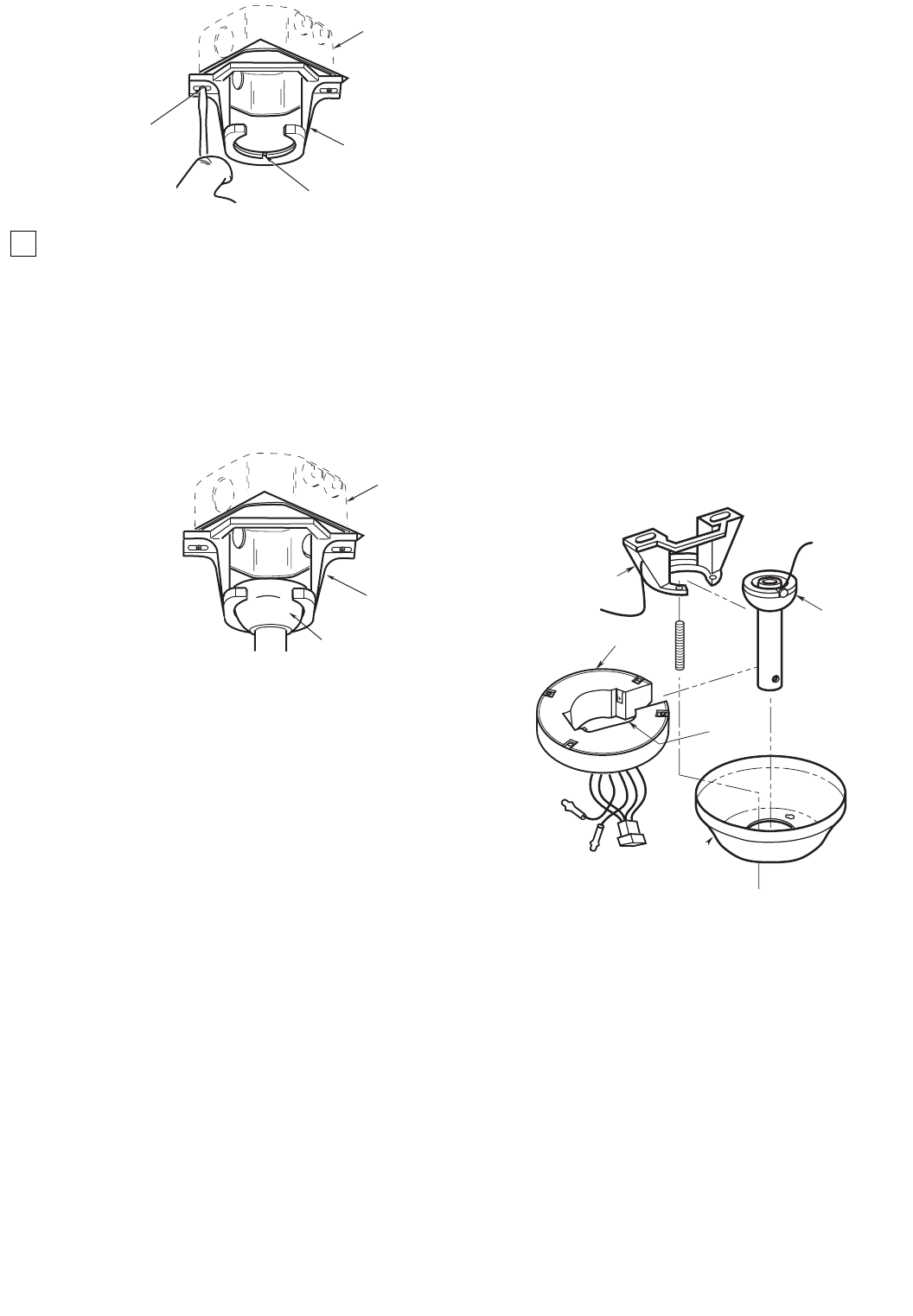
TWO SCREWS
SUPPLIED WITH
OUTLET BOX
HANGER
BRACKET
TAB
OUTLET
BOX
OUTLET
BOX
HANGER
BRACKET
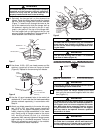
HANGER BALL/
DOWNROD ASSEMBLY
NOTE: CEILING COVER,
SUPPLY WIRES AND
FAN WIRES OMITTED
FOR CLARITY.
Figure 11
Figure 12
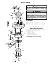
16. Carefully lift the fan and seat the hanger
ball/downrod assembly on the hanger bracket
that was just attached to the outlet box (Figure
12). Be sure the groove in the ball is lined up with
tab on the hanger bracket (Figure 11).
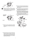
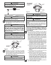
19. Securely connect the wiring harness connector to
the receiver connector, and connect the blue and
yellow wires to the blue and yellow wires from the
receiver (Figure 4).
20. Turn the receiver so that the flat side aligns with
the open side of the hanger bracket (Figure 13).
Fold and position the wires into the space above
the hanger ball and into the outlet box.
21. Feed the wires and connectors around the out-
side of the receiver, through the open side of the
hanger bracket, and into the outlet box. Slide the
receiver up and over the hanger bracket.
Remove the backing on the foam adhesive pads
and press the receiver against the ceiling.
22. To complete the ceiling fan assembly, skip to the
“FINAL ASSEMBLY” section of this Owner’s
Manual.
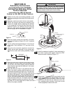
17. Position the receiver (supplied with the SR120
Remote Control or SW140 Wall Control) by pass-
ing the opening in the receiver over the downrod
(Figure 13).
18. Connect the black wire from the wiring harness to
the black (hot) supply wire (Figure 4). Connect the
white wire from the wiring harness to the white
(neutral) supply wiring. Connect the green ground
wires from the hanger bracket and the hanger ball
to the supply ground wire. Use wire connectors
supplied with your ceiling fan.
HANGER
BRACKET
HANGER
BALL
CEILING
COVER
SW375
RECEIVER
FLAT SIDE
OPEN
SIDE