


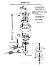
How to Hang Your
Ceiling Fan
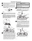
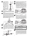
1. Securely attach the hanger bracket to the outlet
box using the two screws supplied with the outlet
box. (Figure 13).
2. Carefully lift the fan and seat the hanger ball/
downrod assembly on the hanger bracket that was
just attached to the outlet box (Figure 14). Be sure
the groove in the ball is lined up with tab on the
hanger bracket (Figure 13).
6
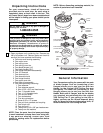
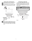
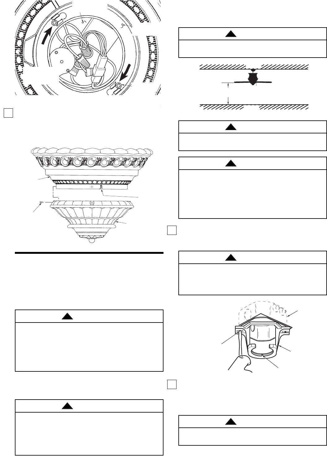
16. Position the lower trim assembly on the upper
cover trim so that the tabs on the lower trim
assembly slide into the slots in the upper cover trim
(Figure 11). Then securely install four 8-32 x 1/2”
screws (supplied).
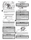
Electrical Requirements
Your new ceiling fan will require a grounded electrical
supply line of 120 volts AC, 60 Hz, 15 amp circuit.
The outlet box must be securely anchored and
capable of withstanding a load of at least 50 pounds.
If your fan is to replace an existing ceiling light fixture,
turn electricity off at the main fuse box at this time
and remove the existing light fixture.
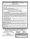
The fan must be hung with at least 7' of clearance
from floor to blades (Figure 12).
WARNING
!
CEILING
FLOOR
AT LEAST
7'
Figure 12
The outlet box must be securely anchored and capable
of withstanding a load of at least 50 lbs.
WARNING
!
Hanger bracket must seat firmly against outlet box. If
the outlet box is recessed, remove wall board until
bracket contacts box. If bracket and/or outlet box are
not securely attached, the fan could wobble or fall.
WARNING
!
TWO SCREWS
SUPPLIED WITH
OUTLET BOX
HANGER
BRACKET
TAB
OUTLET
BOX
Fi
g
ure 2
Figure 13
Failure to seat tab in groove could cause damage to
electrical wires and possible shock or fire hazard.
WARNING
!
To reduce the risk of fire, electric shock, or personal
injury, mount fan to outlet box marked acceptable for
fan support, and use screws supplied with outlet
box. Most outlet boxes commonly used for support
of light fixtures are not acceptable for fan support
and may need to be replaced. Consult a qualified
electrician if in doubt.
WARNING
!
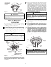
TURN
TURN
8-32 x 3/8"
SCREW (2)
UPPER COVER
TRIM
HOLE FOR SPEED
CONTROL SWITCH
CHAIN
SWITCH HOUSING
ASSEMBLY
LOOKING UP INTO SWITCH HOUSING ASSEMBLY
Figure 10
8-32 x 3/8"
SCREW (4)
LOWER TRIM
ASSEMBLY
UPPER
COVER
TRIM
SLOT
Figure 11
To reduce the risk of fire, electric shock, or personal
injury, mount fan to outlet box marked acceptable for
fan support, and use screws supplied with outlet
box. Most outlet boxes commonly used for support
of light fixtures are not acceptable for fan support
and may need to be replaced. Consult a qualified
electrician if in doubt.
WARNING
!
Turning off wall switch is not sufficient. To avoid
possible electrical shock, be sure electricity is turned
off at the main fuse box before wiring. All wiring must
be in accordance with national and local codes and
the ceiling fan must be properly grounded as a
precaution against possible electrical shock.
WARNING
!