


4
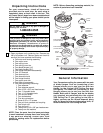
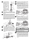
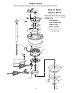
1. Remove the fan motor and housing assembly from
styrofoam packaging and position it so that the top
of the motor is facing you.
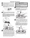
2.Remove the hanger ball from the downrod by
loosening the setscrew in the hanger ball until the
ball falls freely down the downrod (Figure 1).
Remove the pin from the downrod, then remove the
hanger ball. Retain the pin and hanger ball for
reinstallation in step 9.
3. Separate, untwist and unkink the three motor
leads. Route the motor leads through the downrod
and seat the downrod in the motor coupling
(Figure 2).
NOTE: If your ceiling height is nine feet or higher,
you may use the 18-inch downrod, along with the
downrod trim and decorative bulb. If your ceiling
height is between eight and nine feet, you must
use the shorter 4-1/2” downrod.
4. Align the clevis pin holes in the downrod with the
holes in the motor coupling. Install the clevis pin
and secure with the hairpin clip (Figure 3). (Pin and
clip are supplied in loose parts bag.) The clevis pin
must go through the holes in the motor coupling
and the holes in the downrod. Push the straight leg
of the hairpin clip through the hole near the end of
the clevis pin until the curved portion of the hairpin
clip snaps around the clevis pin. The hairpin clip
must be properly installed to prevent the clevis pin
from working loose. Pull up on the downrod to
make sure the clevis pin is properly installed.
5. Install the setscrew (supplied) in the motor
coupling (Figure 3). While pulling up on the
downrod, tighten the setscrew using the setscrew
wrench (supplied).
NOTE: The setscrew must be properly installed as
described above, or fan wobble could result.
6. Screw two 1” threaded studs (supplied) into the
motor (Figure 4). Leave approximately 7/8” of the
stud extending above the motor. Slide the motor
cover over the downrod and rotate the cover until
the threaded studs protrude; install two
lockwashers and knurled knobs (supplied) to
secure the cover.
NOTE: Make sure the connected red leads, the
connected brown leads, and the white lead are
completely inside the motor cover and not
pinched between the motor cover and the motor.
MOTOR
COUPLING
CLEVIS PIN
HAIRPIN
CLIP
CONNECTED
RED LEADS
CONNECTED
BROWN LEADS
WHITE LEAD
DOWNROD
SETSCREW
CLEVIS PIN
MOTOR
COUPLING
DOWNROD
HAIRPIN
CLIP
Assembly Instructions
HANGER BALL
PIN
DOWNROD
SETSCREW
MOTOR COVER
KNURLED KNOB
1" THREADED STUD
7/8"
LOCKWASHER
MOTOR
MOTOR LEADS
(BLACK, WHITE,
AND BLUE)
SETSCREW
WRENCH
FAN MOTOR AND
HOUSING ASSEMBLY
DOWNROD
It is critical that the clevis pin in the motor coupling
is properly installed and the setscrew securely
tightened. Failure to verify that the pin and setscrew
are properly installed (as shown in Figure 3) could
result in the fan falling.
WARNING
!
Figure 1
Figure 3
Figure 4
Figure 2