


5
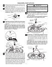
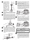
7. If you have installed the
18” downrod, install the
downrod trim and
decorative bulb as
follows (Figure 5). Slide
the decorative trim
(grommet-end first) over
the downrod and seat
the grommet firmly
against the motor cover.
Then slide the
decorative bulb
(oriented as shown)
over the downrod, being
certain that the downrod
trim seats in the bottom
grommet of the
decorative bulb.
8. Position the ceiling cover trim and the ceiling cover
over the downrod. Be sure the cover is oriented
correctly, with the large opening at the top
(Figure 5).
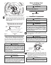
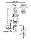
9. Reinstall the hanger ball on the downrod (Figure 6)
as follows. Route the motor leads through the
hanger ball and slide the hanger ball over the
downrod. Install the pin through the holes at top of
the downrod and slide the hanger ball up the
downrod, aligning the ball so the pin is captured in
the groove in the top of the hanger ball. Pull the
hanger ball up tight against the pin and securely
tighten the setscrew in the hanger ball. A loose
setscrew could create fan wobble.
10. The fan comes with blue, black and white leads
that are 80” long. Before installing fan, measure
up approximately 6 to 9-inches above the ball/
downrod assembly. Cut off excess leads and
strip back insulation 1/2-inch from end of leads.
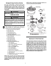
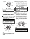
11. Use five 10-32 x 3/8" pan head screws and flat
washers (supplied) to secure the flange to the
blade (Figure 7). Repeat for the remaining
blade(s).
18" DOWNROD
GROMMET
DECORATIVE
BULB
GROMMET
DOWNROD
TRIM
GROMMET
MOTOR COVER
Figure 5
DOWNROD
PIN
HANGER BALL
Figure 6
10-32 x 3/8"
PAN HEAD SCREW (5)
BLADE
FLAT WASHER (5)
BLADE
FLANGE
Figure 7
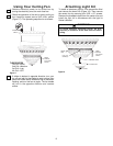
12. Use the holes in the square recesses in the motor
hub marked with "4" and install the blade
assemblies in accordance with Steps 13 or 14.
13. FOUR-BLADE VERSION. Attach one blade
assembly to the motor hub using two 10-32 x 5/8"
oval head screws (supplied) (Figure 8). Do not
tighten completely at this time. Install remaining
blade assemblies in the same way. Gently snug
all flange screws to the motor hub, working
around the hub in a clockwise sequence. Next,
securely tighten all flange screws, again working
in a clockwise sequence. Failure to follow this
procedure could result in fan wobble.
14. TWO-BLADE VERSION. Attach one blade
assembly to the motor hub using four
10-32 x 5/8” oval head screws (supplied)
(Figure 9). Install the other blade assembly in the
same manner. Gently snug all flange screws to
the motor hub. Make sure the ends of the flanges
are engaged, then securely tighten all flange
screws, working in a clockwise sequence.
15. Turn fan assembly over so the bottom is oriented
up. Partially install two 8-32 x 1/2” screws
(supplied) in the switch housing assembly (Figure
10). Slip the speed control switch chain through the
hole in the upper cover trim, then position the cover
trim on the switch housing assembly so that the
two screws protrude through the key hole slots in
the cover trim. Turn the cover trim fully clockwise
and then securely tighten the two 8-32 x 1/2”
screws.
To reduce the risk of personal injury, do not bend the
blade flanges when installing the flanges, balancing
the blades or cleaning the fan. Do not insert foreign
objects between rotating fan blades.
WARNING
!
10-32 x 5/8"
OVAL HEAD SCREWS
(2 PER BLADE FLANGE)
14° FOUR-BLADE FLANGE
MOTOR HUB
Figure 8
10-32 x 5/8"
OVAL HEAD SCREWS
(4 PER BLADE FLANGE)
20° TWO-BLADE FLANGE
MOTOR HUB
Figure 9